• Spring 2024 meetup in Calgary - date Saturday, April 20/2024. discussion Please RSVP Here to confirm and get your invitation and the location details. RSVP NOW so organizers can plan to get sufficient food etc. It's Tomorrow Saturday! you can still RSVP until I stop checking my phone tomorrow More info and agenda
  • We are having email/registration problems again. Diagnosis is underway. New users sorry if you are having trouble getting registered. We are exploring different options to get registered. Contact the forum via another member or on facebook if you're stuck. Update -> we think it is fixed. Let us know if not.
  • Spring meet up in Ontario, April 6/2024. NEW LOCATION See Post #31 Discussion AND THE NEW LOCATION

Lathe part on the mill

Janger

(John)
Administrator
Vendor
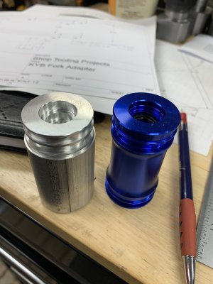
I need to make a part for a buddy. My CNC lathe is still not finished although there was a lot of progress recently. So instead of making this on the lathe I'm doing it on the mill even though it's clearly a lathe part. Here is the original part on the right nicely anodized blue. The left part is my work in progress.
 

Attachments

  • 6EF149FE-0860-4E34-9A89-C9B0DAC02D4E.jpeg
    6EF149FE-0860-4E34-9A89-C9B0DAC02D4E.jpeg
    291.6 KB · Views: 14
Last edited:

Janger

(John)
Administrator
Vendor
First crazy attempt was to reduce the diameter with this realllly long EM in one go. It was incredibly loud chattering I had to put on ear defenders (haha love the British expression). Thanks @Dusty for the EM!
 
Last edited:

Janger

(John)
Administrator
Vendor
Finish was really poor too of course. IMG_0633.jpg


So next idea was to use a vise soft jaw to chuck up on the bat so to speak and do the tricky ends of the part well supported. Finish is much better. I can do the detailed ends one at time flipping the part over to do the bottom. I will have to reduce the "middle" part diameter on the manual lathe but that should be ok.
IMG_0653.jpg
 
Last edited:

Janger

(John)
Administrator
Vendor
This is part cad model - you can see it has a lot of features on the outside and more on the inside - both ends.

Screen Shot 2021-06-23 at 8.26.09 PM.png
 

Janger

(John)
Administrator
Vendor
Here is the soft jaw model. The hole is 1.5" in diameter and 1.875" deep. I modelled it as one block but actually it is two jaws with the split down the middle.

Screen Shot 2021-06-23 at 8.29.25 PM.png
 

Janger

(John)
Administrator
Vendor
I'm using a wood ruff cutter to do the bearing surfaces. This is an earlier picture before I started using the soft jaw. IMG_0632.jpg
 

Janger

(John)
Administrator
Vendor
More still to come! The CAM is fairly involved. I also need to mill out a boss at the bottom of the hole about 2.5" down with a 3/16" end mill. I've bought two end mills for the task and programmed the milling very conservatively. 1 degree helix angle. 5000 rpm. Cutting 0.001" per tooth. 13 ipm. Feed rate too fast? @Alexander ?
I'll have the coolant on full blast down the hole - I think that will lift out the chips but it will be hard to keep an eye on this as it's really blind down there.

Screen Shot 2021-06-23 at 8.46.07 PM.png
 

Tom Kitta

Ultra Member
Hmm, looks like an easy project for manual lathe or am I missing something?

4 outside groves - not a big deal especially in AL. I mean should be doable in like maybe an hour?
 

Janger

(John)
Administrator
Vendor
Made a mandrel today to hold the part for the final lathe ops. Thanks JN and JC for the discussion. Last pic is my part on the left and the original on the right. I still have a few details to get right but it’s coming along.

71CB9AF6-B02E-41C5-A6A4-2E6CF720EDF0.jpeg

55235FEF-19BC-4254-8915-4D6A199D8152.jpeg

381188B2-16EF-4A46-88C0-AEB136F4FE68.jpeg
 

Janger

(John)
Administrator
Vendor
I just learned about a feature in Fusion called Section analysis - it lets you cut away to the inside of a part so you can see what is happening. Really useful. Especially when trying to get the CAM right at the bottom of a hole. I was cutting bodies into two parts and hiding one to see inside - with section analysis you don't have to do that. Using two bodies makes the CAM more complicated. Try -> Menu -> Inspect -> Section Analysis.

Screen Shot 2021-07-03 at 2.55.22 PM.png
 

Dusty

(Bill)
Premium Member
Made a mandrel today to hold the part for the final lathe ops. Thanks JN and JC for the discussion. Last pic is my part on the left and the original on the right. I still have a few details to get right but it’s coming along.

Hey John very nice work. One question why did you use a different material where the mandrel butts up against the chuck and at bolt end?

I assume so you wouldn't mar the finished part to slippage.

View attachment 15798

View attachment 15799

View attachment 15800
 

PeterT

Ultra Member
Premium Member
I use sectioning in CAD extensively. Sometimes its the only way to properly see things, especially with more complex assemblies. Other times you need to define a plane at some specific orientation different than the 3 primary planes and (assuming F360 works the same) any plane can be sectioned. Or a section can be offset from a plane by X amount. Or you can hide certain components but not others & section through that. Or you can save that 'view' for later reference. The possibilities are nearly endless. I use to do a lot of manual drafting so I know how much work goes into drawing things that a computer can bang out in a couple mouse clicks. But they still can't quite do that classic ink & airbrush like you use to see back in the day. That took an artist eye.
 
Top