Ironman
Ultra Member
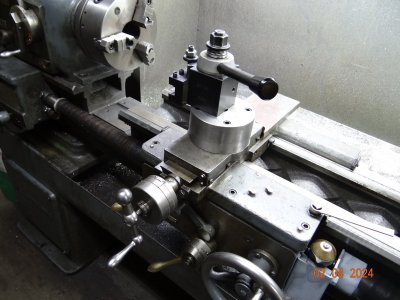
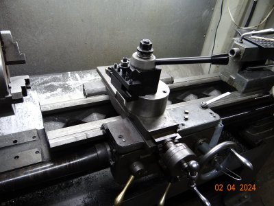
I dug mine out of the mess yesterday and am thinking about using it again. I'm interested in feedback from people who have used this device, and any changes they would make. Pictures are nice too.
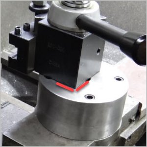
My lathe is a 14 x 48 and the one I made was a round one from some 4" shafting. That's what I had at the time. I have a square block of 3.5 x 5 soft iron now. As I recall, round was a bad idea and prevented close in work to the chuck.. It was more solid but that was a pain that forced me to return to the compound for one job and then it stayed there.
My lathe is a 14 x 48 and the one I made was a round one from some 4" shafting. That's what I had at the time. I have a square block of 3.5 x 5 soft iron now. As I recall, round was a bad idea and prevented close in work to the chuck.. It was more solid but that was a pain that forced me to return to the compound for one job and then it stayed there.