• Scam Alert. Members are reminded to NOT send money to buy anything. Don't buy things remote and have it shipped - go get it yourself, pay in person, and take your equipment with you. Scammers have burned people on this forum. Urgency, secrecy, excuses, selling for friend, newish members, FUD, are RED FLAGS. A video conference call is not adequate assurance. Face to face interactions are required. Please report suspicions to the forum admins. Stay Safe - anyone can get scammed.

Lathe Bed DI Fixture

YYCHM

(Craig)
Premium Member
So, while building my DG D&D knurling tool kit, I found I was....

Noga.JPG


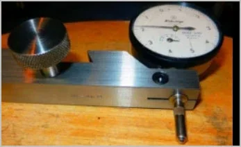
Doing a lot of this..... It was time to make a dedicated DI fixture.

1.JPG


Basically a way clamp that allows a DI to be mounted. That knurled nut appears to secure it fine but if I find it doesn't, I'll drill it through and add a T handle.

2.JPG


Over all it's a bit of a compromise. I really wanted the DI dial facing up (or tilted up) and everything secured from above, but space constraints proved that impossible.

Craig
 
Last edited:
@YYCHM

1 (1).JPG


Nice knurl! Yup, lots of knurls in your future!

I like your simple washer way clamp too. I like simple things.

Ya, the angle on the indicator isn't great. But surely you have enough space to put it on a 45.
 
Maybe time time to invest in a DRO. Aliexpress has some good pricing.

Actually, I had a set of IGaging DROs on it for a couple of years.


Never seemed to use the z-axis DRO and I got good enough with the x-slide dial that I didn't use that DRO either, so I removed them.
 
Actually, I had a set of IGaging DROs on it for a couple of years.


Never seemed to use the z-axis DRO and I got good enough with the x-slide dial that I didn't use that DRO either, so I removed them.
Ha ha... I've got IGaging dros on my lathe and because I've had them, I've never made a DI holder/fixture and also probably why I've never gotten good with the dials! I find them really helpful/useful.
 
If you change the basic shape of the holder to the geometry outlined in red, the face of the DI will be at the same angle as that of the angled face. Keep everything the same as what you have, except machine the angled face and the corresponding threaded hole normal to that face (90* to the angled surface).

You might need some relief on the lower vertical face for the DI body to clear.
85E351AF-A157-4F74-9B16-97063D6C512A.jpeg
 
If you change the basic shape of the holder to the geometry outlined in red, the face of the DI will be at the same angle as that of the angled face. Keep everything the same as what you have, except machine the angled face and the corresponding threaded hole normal to that face (90* to the angled surface).

You might need some relief on the lower vertical face for the DI body to clear.
View attachment 26184

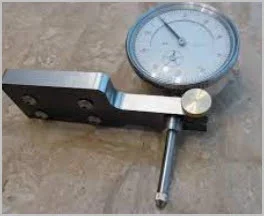
How would that work when the mounting flange looks like this?

DI.JPG
 
Depending on the indicator, you might be able to get a replacement 'lug-less' back plate. Or if its a beater, just remove it & cut/mill it off.
Personally I find lugs to be more of a pain. Most of my systems including home brew clamp on the stem housing. If you had a clamp (maybe where @RobinHood is going) you could swivel face to any orientation & secure it in that position

1662347550745.png
 
How would that work when the mounting flange looks like this?
I made one of those.
AXA-Indicator-2b.jpg

Even went as far as to make a pattern from the 3D print.
AXA-Indicator-2f.jpg

Never did cast it. Don't remember why.
AXA-Indicator-2c.jpg

This could have just been a trial to see if it pulled properly.
 
Examples of stem clamping. I know... more work.
Actually they are not optimal either. The clamp screw should be on the open end side like middle picture, but should have relief hole on other side at end of slit, like right hand picture
 

Attachments

  • SNAG-2022-09-04 9.24.55 PM.webp
    SNAG-2022-09-04 9.24.55 PM.webp
    9.3 KB · Views: 3
  • SNAG-2022-09-04 9.25.09 PM.webp
    SNAG-2022-09-04 9.25.09 PM.webp
    7.9 KB · Views: 3
  • SNAG-2022-09-04 9.25.28 PM.webp
    SNAG-2022-09-04 9.25.28 PM.webp
    10.4 KB · Views: 3
You guys type faster than I do!

Here's my adaptation to hold by the stem in a split clamp for a flat way Myford:

DGM1.JPG


The knob on the front is the way clamp, the DI is clamped by the aircraft bolt (I wanted the clamping power of the 1/4-28 thread) on top and the other knob is for the adjustable rod that lets you bring the carriage to a repeatable stop.

In this view you can see the hole for the DI stem.

DGM2.JPG

I borrowed most of the design elements from a vee ways clamp I saw on another forum so it should be easy to convert it back!

Last photo shows the DI inserted from the other side and tilted for a different view.

DGM3.JPG

This was milled on the Myford in my BM (before mill) days.

D:cool:
 
Last edited:
Back
Top