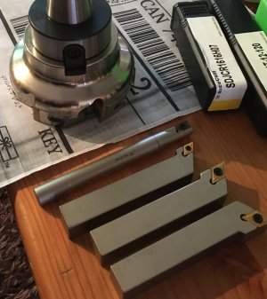
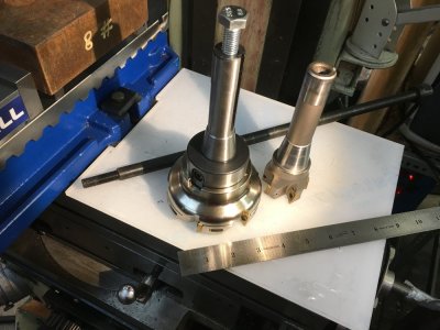
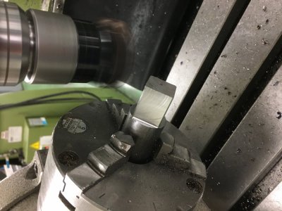
I bought this very nice 100mm face mill from China (company called NiceCutt www.nicecutt.com). I didn't know to tell them and they didn't know to ask what type of draw bar I have. Turns out the tool needs a M12 1.75 thread. I have a 7/16 20 tpi draw bar. I suppose I'm making a new draw bar. Is that typical for european or asian machines outside of USA? Beside is my 2" face mill for comparison. I also bought some lathe tooling and a 1/2" insert end mill. It is nice stuff. I'll post more pictures if people are interested.

-
Scam Alert. Members are reminded to NOT send money to buy anything. Don't buy things remote and have it shipped - go get it yourself, pay in person, and take your equipment with you. Scammers have burned people on this forum. Urgency, secrecy, excuses, selling for friend, newish members, FUD, are RED FLAGS. A video conference call is not adequate assurance. Face to face interactions are required. Please report suspicions to the forum admins. Stay Safe - anyone can get scammed.
You are using an out of date browser. It may not display this or other websites correctly.
You should upgrade or use an alternative browser.
You should upgrade or use an alternative browser.
Imperial vs Metric Drawbars
- Thread starter Janger
- Start date
Ya, for sure, show some of your other goodies.
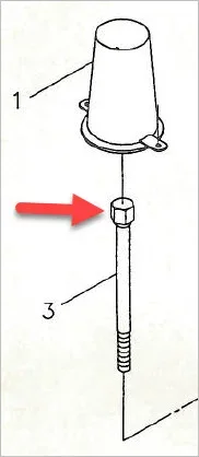
I've never made a draw bar but I've often wondered about what looks like a pin through the upper hex portion of mine. Wondering if its a shear pin of some sort, or just the way they secured the upper hex portion. Aside from that upper detail, looks lie a straight rod with threaded end. I guess make sure your threads are good because that's going to have consensual relations with your $$ tooling.
I've never made a draw bar but I've often wondered about what looks like a pin through the upper hex portion of mine. Wondering if its a shear pin of some sort, or just the way they secured the upper hex portion. Aside from that upper detail, looks lie a straight rod with threaded end. I guess make sure your threads are good because that's going to have consensual relations with your $$ tooling.
Attachments
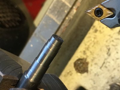
Lathe tooling and big face mill. Diamond shaped inserts. I bought their fancy inserts they claim are high end. I don’t know. My lathe only advances at 0.0039” on the slowest. Perhaps the nose radius isn’t big enough for this power feed setting. It’s not bad but the results dont match the sandvik inserts at sait. The smoothest example is me turning the handle even slower than the power feed. I tried different depth of cut and ran it at the fastest rpm 2000. Same results. That’s a piece of 12L14 too.
I was thinking about making the draw bar I need. I think the hex end is a separate piece and pinned to the shaft so you don’t have a lot of material wasted. Good observation Peter. Would hot roll do for this? Do I need to harden it?
I was thinking about making the draw bar I need. I think the hex end is a separate piece and pinned to the shaft so you don’t have a lot of material wasted. Good observation Peter. Would hot roll do for this? Do I need to harden it?
Attachments
Last edited:
I would probably use cold rolled but hot rolled will work if that is all you have. .0039" is not a heavy feed rate but i realize sometimes these small machines need special treatment to produce an acceptable fininsh. Speeds and feeds from textbooks and industrial sized machines have never worked on my hobby sized machines.
Tom Kitta
Ultra Member
I never used leaded steel but given that it is supposed to be super machinable I expected shiny finish. What I see is what I typically get with gummy hot rolled stuff. I usually try to increase speed or finish off with sand paper to try to make it better. My hard stuff 4145 and 4330 all finish up with mirror shine.
I think China like the rest of the planet uses metric. I only bough once a small face mill many years ago from China. There is no need - you can get Kennametal or similar stuff gently used for cheap from the US. At least you know it comes with imperial threading.
Same thing for inserts - for experimenting you can get them cheap from the US. However, I am starting to see inserts from China for just 50c each now.
Tom Kitta
Ultra Member
I am sure he can make a draw bar - but I feel it would be a pain to change not just the tool but also the whole draw bar each time you need to use metric tool. Agreed the draw bar needs to be made of something that is a touch stronger than gummy hot rolled steel unless you want to make one often or its very occasional use only.
I use DCMT & CCMT inserts. Judging by the 12L14 pic (and its always hard the way camera pics up lighting & makes it look different than real life) I'd have to say you could do better on this grade of steel. Sometimes the larger nose radius does not correspond to better finishes. Or its 'shiny' but under magnification its a series of shiny bottomed scallops as opposed to a more continuous but 'micro-threaded' surface from a sharp nose. For the most part I use 1/32 & 1/64" radius inserts (or whatever the metric equivalent is) which feels almost fragile sharp. The finish isn't appreciable worse, but find I can creep on dimensions better. On leaded steel I leave about a thou over & hand finish. On 1018 hot/cold/crap steel more like .002" allowance. Sometimes on aluminum I call it good unless its a specific fit. I like the sharper ones on aluminum, brass & bronze. I've tried the larger nose on aluminum and it seems better than steel. But my informal test is to keep the same locked carriage setting & just change up the feed. If you can skim the tops off the hills to any appreciable amount, then its kind of indicative that there is a bit of spring left in the setup because of larger cutting force on the larger nose. On aluminum, negligible spring. On steel, more spring. Kind of makes sense & same old story - a rigid, solid setup is probably more important than insert type vs HSS vs magical cutting fluid.
Back to the drawbar, I guess its up to you to decide. For the assembly style heads you could separate the non-standard tooling shanks from their heads & get the ones that match your drawbar threads. But a drawbar is probably not that bad to make & nice to have. I'd practice the threads on short stick of similar alloy you intend to use, especially if its a change to metric threading gears. Get that down pat so you are 100% confident. You want these to be good as they engage the tooling day in day out. I'm really not sure it should be hardened. I thought about all-thread too but you just never see it, so maybe there is a strength issue? I assume the drawbars job is to just suck the tool into its taper seat & that's what is resisting torque, not the drawbar itself? Also have a look area at the base of the hex (wrench) portion. I've never looked close but seems to me its a tapered seat for centering? Maybe that varies by mill.
Back to the drawbar, I guess its up to you to decide. For the assembly style heads you could separate the non-standard tooling shanks from their heads & get the ones that match your drawbar threads. But a drawbar is probably not that bad to make & nice to have. I'd practice the threads on short stick of similar alloy you intend to use, especially if its a change to metric threading gears. Get that down pat so you are 100% confident. You want these to be good as they engage the tooling day in day out. I'm really not sure it should be hardened. I thought about all-thread too but you just never see it, so maybe there is a strength issue? I assume the drawbars job is to just suck the tool into its taper seat & that's what is resisting torque, not the drawbar itself? Also have a look area at the base of the hex (wrench) portion. I've never looked close but seems to me its a tapered seat for centering? Maybe that varies by mill.
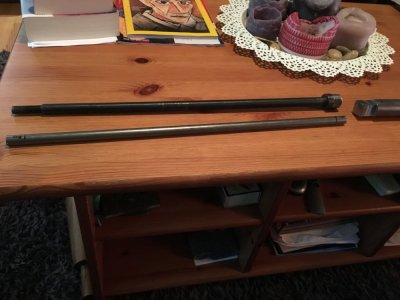
In this version of the photo you can see the drawbar. It's about 16 inches long. It is quite simple.
To make a new drawbar instead of using a single point tool to make the threads I am going to try using a die held against the tailstock which is the technique we used in SAIT class MACH213 for threading the hammer handle. It is quite a bit simpler but we will see how it goes.
I also thought about welding on a metric bolt to some stock and then turning down the head on the lathe. I'm not sure how much it would anneal doing that. Has anyone ever used that gold smith trick of submersing half the part in water and welding the part above? Maybe the water would just burst into steam.
Good discussion thanks everybody.
Attachments
Last edited:
Tom Kitta
Ultra Member
My old Kerney&Tucker has a draw bar made from threaded rod with some nuts welded at one end.
If someone has time to play & wants to make it into a project I guess turning larger bar down and making hex at the end seems easier then getting somewhat expensive hex stock and turning it down.
I don't think accuracy of the turning of the draw bar matters - as long as its round (i.e. not off width) it doesn't matter one end is bigger than the other as the purpose of the draw bar is to get stuff into taper and to spin. So at high speeds what matters is that it is round and straight. If it is not straight or off-round at very high speeds it may vibrate enough to matter. Then again for manual machine it probably would need to be visually bent and at top speed to be noticed.
More attention should be paid to the length of a draw bar - you want enough thread to get tool into taper - but too long and you may have tooling that will not work as it has threads that go only so far. I guess if you make draw bar too short you have a problem as longer one can be shortened to size.
I am intrigued by this submersion technique
Update: submerged welding is a thing but it does not involve water! Still looking
Mike did you find anything on this topic? When I google I just find loads on submerged arc flux welding where the arc is buried under loads of powdered flux. That's an interesting topic too but not what I mean here. I also find lots on divers doing underwater welding which is also not what I mean. I'm not sure what this technique is called. The idea is to keep some of the part cool while you work on another part of the part at high temperature. I know gold smiths do this with a water bath to resize rings and protect the stones etc. Anybody know what this is called if it is a technique viable with welding?
The thing that concerns me about that (and I am no welder) is - presumably you be putting the all-thread segment into a tight fitting blind hole & welding the fillet? But initially you don't have constant thread material exposed like a shaft within a shaft because of the helical thread Vee. So presumably the first weld bead would have to follow in & out (irregular) until the fillet is established. You could get the weld established no problem, just wondering if heat might be unequal & assembly might distort & introduce run-out?
Cold assembly: If the hole was tapped into the rod & all-thread screwed in with permanent retaining Loctite & cross pinned, its probably not going nowhere. But now you are into the job for a tap plus chuck of all-thread & probably more effort & chance of run-out that single point or die threading a turned down boss... which leaves you a 100% solid metal part.
I think I've seen these cheaper but just cant find the link. maybe as part of a power drawbar kit? You would have to confirm the length but even if you had enough round section protruding up the topside, you could cut it off & fashion your own wrench hex to suit your spindle length?
https://www.ebay.com/itm/Spline-Hea...454844?hash=item460ef20d3c:g:ekQAAOxySE9Q7haW
Bofobo
M,Mizera(BOFOBO)
No john i watched likely the same vids as you seen, very neat indeed, I
having worked (destroyed) a few jewelry peices myself trying to size them i would love to know more about it unfortunately ive been re building bikes all week and almost forgot to keep looking lol im going to swing my search into just goldsmithing videos on an attempt to find an example. Noble metal, ferrous metal, its a metal work forum and sounds like a great "box of tricks" technique even if only used once in a lifetime.
having worked (destroyed) a few jewelry peices myself trying to size them i would love to know more about it unfortunately ive been re building bikes all week and almost forgot to keep looking lol im going to swing my search into just goldsmithing videos on an attempt to find an example. Noble metal, ferrous metal, its a metal work forum and sounds like a great "box of tricks" technique even if only used once in a lifetime.
Working on the square nut for the metric drawbar in class at sait. I’m going to tap it 1/2”-13 and thread same on some cold roll 12l14 roundbar 1/2” I found under the bench. Then insert and thread lock the bar into the nut. No welding. This is how it’s done on my existing drawbar. And thread the other end of the new drawbar M12 1.75.
As a different approach I was considering welding the threaded section of a M12 bolt to the end of the drawbar so I had a hardened thread. that seems pretty tricky though. Distortion and annealing likely? I think peters suggestion of using drill rod and hardening that is better. Maybe if the 12l14 does not wear well I’ll do that.
As a different approach I was considering welding the threaded section of a M12 bolt to the end of the drawbar so I had a hardened thread. that seems pretty tricky though. Distortion and annealing likely? I think peters suggestion of using drill rod and hardening that is better. Maybe if the 12l14 does not wear well I’ll do that.
Attachments
Last edited:
I made a new drawbar for my mill using 7/16" cold roll rod. I single point threaded the bottom end and used a long nut meant for joining 1/2" threaded rod pieces together at the top. With just a very light skim on the ID of the nut with a boring bar it was a slip fit over the 7/16" draw bar rod. I drilled six 5/16" holes through the flats on 3 sides of the nut to provide access to pocket weld the nut to the rod. I also welded it across the top. I checked the welded assembly in the lathe for runout, it has almost none. I machined the flats of the nut to make them flat and fit an 18 mm socket. I then machined a spacer with a pilot extension on one end to match the original draw bar and keep the drawbar centered in the spindle. I've been using it for 2 years now with no problems. I used cold roll steel so the draw bar is softer than the collets and it is sacrificial. Here are some pics of the original and new draw bar.


Last edited:
I like Johns method.
I've been trying to find a typical hardness values for common bolts & all-thread shafting but it seems to vary. All I know is you can file & machine even high quality high strength bolts so they cant be that high. I would think it would be advantageous to drawbar threads being slightly softer than the EM holder/collet etc. because there is more money tied up in the tooling than a chunk of rod & hex stock for the drawbar.
Also, I've never really understood, what exactly is the purpose of the oversize chunk on the top side? Looks like it nestles inside the spindle but why the deep counter bore vs. just a constant diameter hole & so the drawbar would just be a rod with tightening nut on top?
Tom Kitta
Ultra Member
Mild steel is around 120, 4140 is around 190 and my 4330 is a whopping 280.
280 on a different scale is 31/32 which is a realistic limit for tapping holes with HSS. This is all for normalised condition. The first one is Brinell scale. Second is HRC.
4330 in annealed condition is plenty hard for most needs. Accidental hardening like via welding make it virtually immune to any HSS whatever with cobalt or not.

