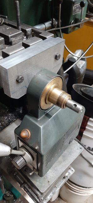
I am making some progress installing the power feed on my X axis for my milling machine. The support mount is completed, just need to clean up the edges to size. This week-end I will make two 3/4" -20 retaining nuts to secure the lead screw via some thrust bearing.
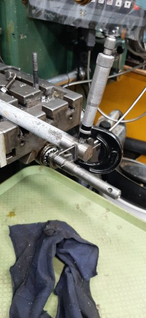
Then I need to secure the bevel gear to the lead screw. The bevel gear has a 5/8" bore with a 1/8" keyway. My milling machine lead screw is 5/8" but doesn't have a keyway feature and no threads to secure the bevel from sliding in the keyway. Would it be acceptable to drill a hole through the bevel gear shoulder and lead screw and then put a
1. 1/8" spring pin , or 1/8" aluminum pin which could shear in case of emergency Doh!
2. drill and tap the bevel gear shoulder for a set screw which locks to the lead screw
OR
3. remove the lead screw cut a keyway slot, reduce the diameter of the end of the lead screw, cut a thread for a locking nut to secure the bevel gear and make a new handle for manual use.
I like option 1 and 2 because I don't need to heavily modify the existing lead screw, I need just one through hole or a dimple for the set screw. To make sure I have the proper spacing meshing between the bevel gears I would put a .030" shim before drilling the hole and then adjust the shim for a 2 degree movement of the bevel gear meshing.
So far all the power feed I have seen don't have set screws or through pins. I thought it would be a good idea to ask for your thought before I do the irreversible.
Any advise is appreciated
The picture shows the end of the lead screw and the long bevel gear shoulder with the thread use for the locking nut for the .125" scale dial.


