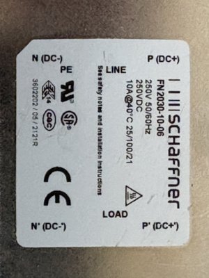
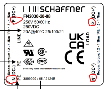
I have a Schaffner FN2030-10-06 EMI filter. I can see where it goes in the attached PDF. Note that it is the exact part number as in the diagram.
Tech specs are here:


The wiring diagram shows the EMI filter in line before the DC power supply. But the label on the filter clearly says N (DC-) and P (DC+) Load side and the same for the Line side.
Before I install this thing I want to make sure that I'm not going to let the magic smoke out by connecting it the the 240V AC line and load.
Tech specs are here:


The wiring diagram shows the EMI filter in line before the DC power supply. But the label on the filter clearly says N (DC-) and P (DC+) Load side and the same for the Line side.
Before I install this thing I want to make sure that I'm not going to let the magic smoke out by connecting it the the 240V AC line and load.

