• Spring 2024 meetup in Calgary - date Saturday, April 20/2024. discussion Please RSVP Here to confirm and get your invitation and the location details. RSVP NOW so organizers can plan to get sufficient food etc. It's Tomorrow Saturday! you can still RSVP until I stop checking my phone tomorrow More info and agenda
  • We are having email/registration problems again. Diagnosis is underway. New users sorry if you are having trouble getting registered. We are exploring different options to get registered. Contact the forum via another member or on facebook if you're stuck. Update -> we think it is fixed. Let us know if not.
  • Spring meet up in Ontario, April 6/2024. NEW LOCATION See Post #31 Discussion AND THE NEW LOCATION

Help understanding machining tolerance

To start, I'm a hobbiest amateur.

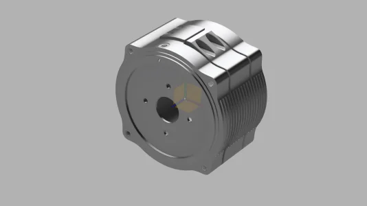
I have a component that I have modeled. I'm looking to have this sent off and machined but I'm not sure I understand machining tolerances etc.

There are a few things like the 4 peripheral mount holes, central mount holes, center bore that need to be maintained within a reasonable tolerance.

This is where my understanding of tolerance falls apart.

The largest dimension of this unit is about 97mm
If I get it machined to a tolerance of 1/1000 then the largest dimension of the bolt holes should still working out...
...But This can't be how things work out. This would mean that any part that needs even slightly better tolerance over a certain size would not be possible to manufacture.
...So this is not the correct understanding. There must be a level of tolerance lower than 1/1000 that would get me a component that still fits well within my needs.

Finally to my question:
What level of machining tolerance does one need for a component? More importantly, how is it defined and how does it play out on a component such as this? Motor mount v12.png
 

RobinHood

Ultra Member
Premium Member
Another thing to look at: are there components within /with which your part interacts? And how is that interaction. For example: is there a shaft inside a bore that needs to be a sliding fit, a close tolerance sliding fit, a non-moving locating fit, a press fit, or a shrink fit?
In other words, tolerances depend on the application as well. And you can have different tolerance specs within the same part. Some parts are made from a casting - so the outside can be -/+1/8” or more and yet contain features that are within 1/10000” or better. Gear box housings come to mind, as an example.
 

historicalarms

Ultra Member
Just a sort of flippant comment after spending a minute looking at your item....from a "hobby machining standpoint" the most relevant tolerance issue may quite well be the "frustration tolerance" you personally have....In my case I may just throw a few tools around the shop or a couple through a window before I begin....just to get that formality over with right away....

Seriously now, I do look forward to a "build progression" postings & the finished item.
 
Another thing to look at: are there components within /with which your part interacts? And how is that interaction. For example: is there a shaft inside a bore that needs to be a sliding fit, a close tolerance sliding fit, a non-moving locating fit, a press fit, or a shrink fit?
In other words, tolerances depend on the application as well. And you can have different tolerance specs within the same part. Some parts are made from a casting - so the outside can be -/+1/8” or more and yet contain features that are within 1/10000” or better. Gear box housings come to mind, as an example.

In my case this piece will only be bolting up to mate with a different component. Nothing like you describe for a shaft/bore scenario.
 
This would be a good place to start.

Thanks for the link!


But what I it still dont understand is if the machining tolerance is for example 0.02mm Then will my part have a possible "growth" or "shrinkage" of 0.02mm/mm or 2% across a critical dimension?
2% difference across the bolt hole mounting locations will put me out almost 2mm which would mean it's a useless part... This is the thing I'm having trouble grasping.
 

Tom Kitta

Ultra Member
0.02 is a very prices bolt hole making. I would say overkill. If things were done so precisely we would not have had need for mating surfaces and set screws as I also assume threading would be ultra precise, bolts would be precision made etc.

when two holes are nominal 10cm apart and tolerance is +- 0.02mm it means the holes will be at most 10.02mm apart and at least 9.98mm in actual part. Given that say mounting is done with M8 bolts the drills themselves will drill holes bigger then needed for M8 by more then the positional accuracy demanded by 0.02. I.e. when a drill drills the hole it has size tolerance and usually drills bigger.

Also the bolts you would use - I assume standard ones are not "perfect" - the thread engagement - i.e. how much space there is for a wiggle room between mating threads is probably something like 60-70%.

0.02mm between bolts may be correct if the product is the size of say matchbox. Or a small PCB. Now drills themselves are 2mm.

Finally, realize that most manual machines have dials set to 1 thou in NA - which is 0.025mm. Yes with a DRO you can try to do better but 1thou is considered limit for these machines. Yes Dabbler or others may cut on a lathe to less then 1 thou but mere mortals like me switch to "sand paper" - i.e. we lap to get better accuracy.

When I tested my DRO to tenths, the mere temperature changes, machine releasing stresses, my breathing or me just moving around were enough to change things by as much as 0.0005 mm.

Hobby CNC machines are generally considered good when they hold 1 thou accuracy.

Great reply, thanks for the insights!

Now to my fundamental misunderstanding. How should I be interpreting a quoted tolerance of +/-X.XXmm when it is quoted? Is that the tolerance between to points 10mm apart 100mm apart? And how does that change with a whole number of features on a certain plane or 3-dimensions relative to one another?
 

PeterT

Ultra Member
Premium Member
https://mae.ufl.edu/designlab/Lab Assignments/EML2322L-Tolerances.pdf

This is a subject unto itself but just informal comments to get you started.

A tolerance is typically applied to a dimension and a dimension is usually stated on a drawing that would (in your case apply to or correspond to a model). So by specifying 10mm +/- 0.5mm that means you will accept that finished part to measure anywhere from 9.5mm to 10.5mm, 10mm being the nominal target. If you spec 100mm +0.5 -0.0 that means you will accept 100.0 - 100.5mm. Whether that dimensional range makes sense to your application is completely in the domain of you the designer using established principles & practices. If you design a shaft that a commercial bearing must go on, you first need to know the min/max of the bearing & desired fit. So the shaft OD (and finish) is a dimensional end result, not a starting point. If your part must marry an existing bolt pattern than logically it must have at least corresponding tolerance or risk not fitting. Where it gets more complex is combinations of tolerances, for example center to center distance is one constraint, but bolt hole diameter itself is another constraint. If the holes are to encompass bolts, we can refer to tables of established clearance hole diameters. But if they are matching dowel pins now we have tighter allowable range & need to be more prescriptive about distance, diameter and hole finish (reamed vs drilled). So it really is application dependent.

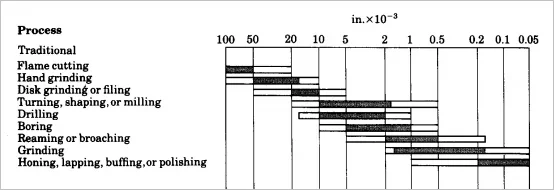
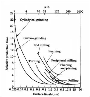
Next concept is datum. You might accept a hole pattern with tolerance X, but its important to be spaced Y amount from this specific surface but you don't care about another surface. So that datum surface must be prescribed in drawing & its physically what machinist will reference off of. We do this so we don't fall in the trap of overdefining the part with crazy dimensions like 1.234567" even though the CAD program can spit out doesn't mean we want to pay someone for a micron finish (unless that's what we want). You can find many charts like below that provide rough idea of tolerances based on common machining methods. Cost go up exponentially to the right so the trick is to only pay for what you need.

At minimum, if you are just going for rough quotes where often the shops don't even want to see your drawings unless certain key features need to be addressed. They might just load the model part into their own CAD/CNC/pricing models & come up with something kind of generic with a catch-all +/- tolerance, probably a function of their machine capabilities.

1623264644532.png

Then there is finish which is yet another spec (and cant contradict dimensions), but leave that topic for now.
1623265168900.png
 
Last edited:

Tom Kitta

Ultra Member
I am no expert but from reading diagrams for backing plates usually important stuff is given its own tolerance. Thus say size of a bore for lathe spindle mating surface will be given as its own tolerance of say +0.01mm.

There can also be "general" tolerance for all other parts of say +- 0.02mm.

So on a diagram you will have two important points apart and distance between them will be marked as 10mm nominal + 0.01 tolerance. All other points will be also shown with distances between them but tolerance will be assumed to be "general". At least this is my understanding.

Unless you part is tiny or something that needs precision I would not worry about it too much. Certainly if its for NASA you better know things precisely.
 

Mcgyver

Ultra Member
Now to my fundamental misunderstanding. How should I be interpreting a quoted tolerance of +/-X.XXmm when it is quoted? Is that the tolerance between to points 10mm apart 100mm apart? And how does that change with a whole number of features on a certain plane or 3-dimensions relative to one another?

Peter gave a lot of good information.

"+/-X.XXmm" means exactly that, that whatever dimension its applied to on a drawing, the part can be X.XX over or under that dimensions Whether the dimension is 10mm dimension or 100m dimension doesn't matter...if that is the state tolerance. Think of the tolerance as applying to a specific dimension on a professional drawing there should either direct or indirect indications of the tolerance for every dimension.

Its really easy to get if you understand their function. Nothing made is "exact", there is always variance. Tolerance is just defining the acceptable limits of the variance . Say a shaft needs to be a sliding fit in a hole. 1" nominal diameter. You could state the diameter as 1" dia, + 0.000" -0.001 and the bearing ID at 1.001" -0.000 + 0.001 (or 1.000 +0.001 + 0.002, conveys the same thing). if the shaft and bearing were made to those tolerance (the actual measurement was in between the allowable limits of the tolerance) you get sliding fit guaranteed to have .001 - .003 clearance. If you need the clearance to be more exact, you tight up a tolerance

As practical matter, for any given dimension, smaller tolerances cost more - either money if you paying for it or time if you machining it. So good design means to only be as precise as you need to be for each dimension.

You'll also find that most correctly done drawings don't have one tolerance. There often ranges of tolerances specified in call out and there conventions such as the number of decimals displayed convey the tolerances. For example, a large fabrication might have a 1/16
tolerance overall, but a specific machined bore might be stated at -0.0 +0.001. Being pedantic, you don't have state 0.001" as a tolerance, you a need two figures, and upper and lower limit - there are various conventions around how to state it, but there is supposed to be an upper and lower limit. Else ambiguity is created - e.g. machining to a thou. does that mean +- 0.001 or does it mean +-.0005? The former allows a range of .002...sounds like machining to 2 thou :). Might not matter for conversation but it does to get a bearing fit correct.

Lastly lots of times for home shop drawings, model engines etc drawings are not toleranced. I do drawings this way somewhat on purpose for two reasons. First, commercially its black and while. If you can't hold a tolerance you don't bid whereas at the home, depending on equipment, abilities and whats acceptable to you as an outcome, there is more than one right answer. After all the customer is the maker. Secondly, what really matters for one of's, model engines etc, is the fit. That's a world of difference at home vs when parts from one shop have to fit those from another. If it matters, I try to convey fits and let the builder, depending on equipment etc, determine how they get there. This adds some decision making burden to homeshop practitioner, to figure whats good enough, but I think it works better for us than the production style tolerancing of drawings
 
Last edited:

PeterT

Ultra Member
Premium Member
Maybe where OP question is coming from, not sure but FWIW - I've also sent a few 3D model parts off to (CNC) fabrication places for price quote. Sometimes just to get you in the ballpark they will state their machine capability like +/- 0.001" So 'theoretically' your 3D object could be made to that tolerance presuming a whole bunch of variables that is basically within the domain of the machine operator. So how the datums are referenced, how tools are chosen, what sequence of operations... is all under the control of the fabricator. They may mill a round hole as opposed to grabbing a drill & reamer from the tool changer. Or thread mill a hole vs tap. All that is under their domain as long as the end result is acceptable.. We have knowledgeable CNC folks on the forum that could do a better job elaborating. But I'm trying to say when it comes to jobbng out to CNC places they might offer something like an all encompassing tolerance factor that is different than older generation manual machines.

And similarly I've seen where a 'typical' surface finish is referenced. But what they might be indirectly saying is their selection of tooling typically yields X finish so that's what you unless there are stipulations. This really needs to be examined closely depending on the application because you can have combinations of surfaces that are on spec but don't make sense in real life. For example curvy mold surfaces that are contour milled & show toolpath stepover. So best to convey end use & ask lots of questions along the way & hopefully teh shop will work with you as opposed to take your money & say this is what you asked for.

What is your part if its not confidential to mention?

I have an electric motor on my mountain bike. The cycloidal gear reduction was damaged and I needed to mate a new reduction unit(planetary) to the said motor. Which means I need to create a brand new housing for the motor onto which the new planetary reduction can mate. That's what this piece is.
 

RobinHood

Ultra Member
Premium Member
In that case you may want to provide both the motor and the planetary to the shop so that they can check fit/tolerances for the mating parts and make your adapter accordingly.
 
A little late to this thread, 0.02mm is less than 0.001" (sorry I understand and use both but from a dimensional standpoint conceptualize inches better). At these or smaller tolerances start to worry about temperature as it greatly effects your dimensions. Bolt hole dimensions and their respective holes are definitely more tolerant. Consider a #8 has just less than 0.001" between tight and normal vs 1/2" which is about 0.015". In both you could go even larger.

So consider what you are doing and how you go about setting it up. Is the dimensions are in difference materials you will have to compensate for expansion/contraction with temperature in the structure.

In most cases unless it very specific a loose tolerance is more than acceptable.
 
Top