• Scam Alert. Members are reminded to NOT send money to buy anything. Don't buy things remote and have it shipped - go get it yourself, pay in person, and take your equipment with you. Scammers have burned people on this forum. Urgency, secrecy, excuses, selling for friend, newish members, FUD, are RED FLAGS. A video conference call is not adequate assurance. Face to face interactions are required. Please report suspicions to the forum admins. Stay Safe - anyone can get scammed.

Helical cut gears - design solutions for lateral forces.

Perry

Ultra Member
I will get straight to the point. How do you/they handle (adjust) for the lateral forces created when using helical cut gears?


The rest of the story.

I have a gear box that has an input shaft from an electrical motor. The gear box reduces the speed of the motor. The input shaft is on two deep groove ball bearings and has a helical cut gear.

An idler gear is also helical cut to mesh with the input shaft gear and is mounted to a shaft that also is on two deep groove ball bearings.

The third gear is helical cut to mesh with the idler gear and it is the output shaft of the gear box. Supported by two deep groove ball bearings.


So far straight forward. When you power up the motor it will cause lateral movement in the input shaft causing it to move to the right due to the helical cut gear.
The idler will move to the left and the final drive will move to the right.

Now I throw a twist into the gear box. The output shaft can back drive the gearbox and drive the motor as a generator. When back driving the system the helical cut gears will move in the opposite directions. The final drive moves to the left, the idler to the right and the input to the left.

Under constant load the gears are in their happy state. When switching directions, the lateral forces in each of the shafts change direction and take up any free play. (usually with a clunk added).

Will shimming the lateral free play effect (or is it affect?) the mesh of the gears? I know in straight cut gears the proper mesh of the gear is important. Usually moving the gears in and out (radial) from each other in a parallel motion. With a helical cut gear I'm sure there is an ideal mesh in and out (radial) from each other, but something makes me think that the lateral play will also come into the picture.


On a side note. From the SKF bearing site, a deep groove ball bearing can handle radial and lateral loads.

Edit.... added an image to give a visual to the loads. Blue radial. Red lateral.
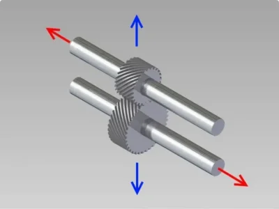
Screenshot 2024-08-03 at 03-53-06 Straight-Cut Gears The Advantages And Disadvantages News Ca...webp
 
Last edited:
Is this something you are designing or it exists? Deep groove can handle axial loads to some degree, might be ok if always in the same direction (there is a bit of play).

If you are designing, helical gears do create an axial load which means you need a thrust bearing or a bearing that constrains radially and axially (angular contact pairs for example). An easy solution are the double row AC bearings, acts like two AC's back to back but in one package. Maybe not good enough for say a spindle, but plenty good enough lots of other things (I've used to mount feedscrews for example)

 
Last edited:
It is something that already exists. I'm thinking I might be able to shim the bearings on one side to remove some of the lateral play in the shafts, but for some reason I think this will cause an issue with the meshing of the gears. I'm even thinking that only shimming the input and output shafts might be the right answer. Allowing the idler shaft gear to float should be ok as it will fall in between the other two gears automatically.


I built a spindle once and used two AC bearings back to back. Had to remember to orient them in the correct position on installation.

Here is my poor mans spindle. lol.
 
Last edited:
a thrust bearing or thrust block would be the solution if the thrust forces are high enough, usually pretty easy to implement
 
Maybe a video will help you guys see what I'm up to.

Here is a short clip of the driveshaft from this gear box. Under power you can see the helical gears pull the shaft to the left. When you release power and the back wheel drives the gearbox the shaft moves to the right.


There are three shafts in the gear box and I am sure all there are probably doing the same thing.

Inspection of Old Gear Box.jpg

I can measure about 0.014" lateral play on the input shaft and about 0.016" lateral play on the output shaft.

Old Gear Box input shaft lateral play.jpgOld Gear Box output shaft lateral play.jpg


I'm thinking I might be able to make a couple shims to place in the gearbox lid bearing recesses.

Thoughts?


The whole point is to get a smoother/quieter transition from the power on to the power off and back drive engaging.


Cheers, P
 
Herringbone cut gears or dual helical cut gears should cancel out the lateral forces. The gears are about 10mm thick. Might be a challenge to cut something like that.

Straight cut gears would also remove the lateral forces, but then I'm trading one noise for gear noise.
 
I think your theory is sound. To eliminate it you could hold both shafts with a preloaded bearing arrangement, e.g. AC's but reducing the play should reduced the clunk, but that obviously is a major undertaking and likely not be possible with the existing parts/geometry.

So its just power on/off, i.e. not reversing, that is the issue? Wonder if the right stack of belleville washers would create a bit of preload so the shaft stayed at the end where you wanted it?
Might be a challenge to cut something like that.

Yes, but doable. To make those helical/herribone gears and have them quiet, you'd probably have to hob them (generate them vs using a form cutter). Not impossible in the home shop, the late John Stevenson did so by electronically coupling the milling shaft with work rotation (he used a universal mill to get the feed the work at the hob's helix), but its a bit of a set up.

For interest and tribute to John, Here's a couple of his photos showing his electronic hobbing arrangement.

For spur gears the feed is at the angle of the hob's helix (done on a universale mill)


hob indexer4.jpg

for helical you angle the feed at the hobs helix, and angle the work to the feed by the gear's helix angle

hob indexer11.webp

hob indexer18.webp


diy generated herribone gears, this imo is earned bragging rights deserving of several pints worth of approbation.

hob indexer14.webp
 
Last edited:
It is power on/off ......but it does reverse the gear box loads.....not the direction of rotation.......when the power is on the motor feeds the gearbox and drives the back wheel. When the power is off the back wheel drives the gear box (Reverses the loads on the helical cut gears. Gears are rotating in the same direction but because of the slope of the tooth on the gear it will feed the lateral forces on the shaft in the opposite direction.) and the gearbox back drives the motor. (Regenerative braking).


The shimming brings me back to my original post.

"Will shimming the lateral free play effect (or is it affect?) the mesh of the gears?"


diy generated herribone gears, this imo is earned bragging rights deserving of several pints worth of approbation.

Very nice. :) Is that two separate helical gears placed back to back? I've seen a few online done like that but there is usually a gap between the two separate gears.
 
"Will shimming the lateral free play effect (or is it affect?) the mesh of the gears?"

For parallel shafts, Yes and No. No to depth of engagement, as doing so doesn't change the distance between shafts, it would just cause one shaft to rotate. Yes in that obviously the two gears have to be in the same spot, i.e. the sides should be parallel, so axial movement will affect his. If you moved them both the left .020", no change. I you moved one ,020 and not the other, the two sides are no longer coplaner so the full width of each gear is no longer in contact. That likely won't matter for 0.020", but at some number it will
 
Ok, that makes sense.

I am unable to measure the play on the center gear. Maybe with some clay and preloading either the input or output gear to get the center gear to shift to its extreme I could get a rough estimate.

My idea is to shim the input shaft to the left. Shim the output shaft to the left. Leave the center gear to "float" between the two.

The other idea was to mess with the cover of the gear box and add in some type of adjustment mechanism to preload the bearings. This gear box is not easy to get in and out and this would give me unlimited chances to adjust it with out having to pull the gear box out and apart each time.
 
You didn't like the bellville washer idea? Its the way some lathes (unimat 3 comes to mind) create preload so they use deep groove bearings (instead of more expensive AC's)
 
Basically I would be doing the same thing, shimming the shaft to one side, but the shim would have a bit of "flex" for lack of a better word?

I'm not sure if I could get one thin enough? Presently I have ~0.015" play. Even if I could one thin enough, do you think it would last? I have not played with these or used them before.

I will have to read up more on these this evening. See what is available.
 
@Mcgyver, I did read up on the Bellville washers. Looks like a great idea, but I can not find any in a 6004 or 6005 bearing size that would fit into the 0.014" I have available.

In my reading about them I did read that it is preferable to load up the outer race of the bearing. No explanation on why.

This got me thinking about where the best location is to shim my play out.


Cleaning everything up this evening and taking a good look at the pieces I noticed that bearing locations in the cover for the gearbox have what looks to be brunishing/hammered type markings on them. My guess is this is where the bearing race has been banging up against the case cover.

The brearings on the main gearbox casting all seem to have a small bit of black rubbery sealant. I would think this might be the sealant for the case halves and some sloppy assembly but one bearing has a fair bit and looks like is was potted into its location.

Looking at the shafts, it looks like there is enough shoulder on the main gearbox side for the shaft to float in the inner race of the bearing. So maybe these bearings are fixed in location. The bearings on the lid side of the shafts look like the outer race float in the lid casting.

I'm hoping to try and find some 0.010" bearing shims to try out my plan. (That is unless I can find some 0.015" bellville washers). I will place them on the lid side of gearbox, under the input shaft and the output shaft only. Loading up the outer races of those bearings.

Unless someone here has a better idea.....or sees a flaw in my plan. :)

And here is a few pictures to keep your interest.

20240807_054110.jpg20240807_054118.jpg20240807_054143.jpg20240807_054154.jpg20240807_054207.jpg20240807_054416.jpg20240807_054450.jpg20240807_054532.jpg
 
Also, can anyone explain the purpose of having bearing sheilds/seals inside and oil filled gearbox? I would think these would not be needed.
 
I have no idea the application, but depending on temperature changes, don't remove all the slack. If this is a gearbox for something that gets hot, an 8" shaft for example increasing its temp 100F will grow about 10 thou. Another reason for the bellevilles, but if they don't fit, they don't fit.
 
Last edited:
Might these work: Bellville Disk Springs for Ball Bearings?

One finds them in electric motors to pre-load the rotor shaft bearings.


IMG_2692.jpeg

Edit: you might have to make the bearing bores a bit deeper to accommodate the washer.
 
Last edited:
Another option is to machine the case down for zero clearance (or even slightly negative clearance) and use the desired thickness of gasket between the halves to give the required end play.

I have seen this in tractor gearboxes bearing caps to adjust shaft endplay.
 
I made a selection of brass head shims for my radial engine of varying thickness from sheet shim stock. I think you can get bronze as well. A little bit of upfront fixtures from scrap aluminum, but the nice thing is you can sandwich a bunch of different sheet thicknesses together & make a bunch all in one go.
 

Attachments

  • 03.jpg
    03.jpg
    45.1 KB · Views: 4
  • 05.webp
    05.webp
    15.4 KB · Views: 4
  • 07.jpg
    07.jpg
    44.9 KB · Views: 4
Back
Top