• Scam Alert. Members are reminded to NOT send money to buy anything. Don't buy things remote and have it shipped - go get it yourself, pay in person, and take your equipment with you. Scammers have burned people on this forum. Urgency, secrecy, excuses, selling for friend, newish members, FUD, are RED FLAGS. A video conference call is not adequate assurance. Face to face interactions are required. Please report suspicions to the forum admins. Stay Safe - anyone can get scammed.

Gear clearance

Matt-Aburg

Ultra Member
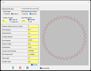
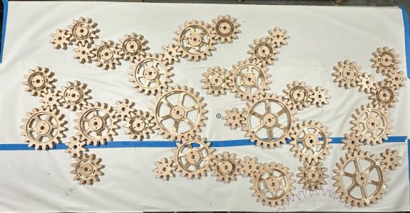
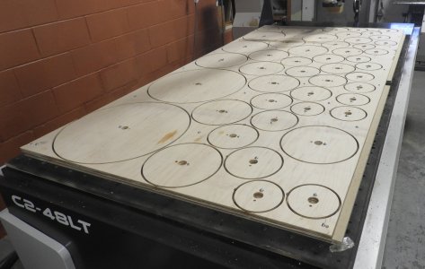
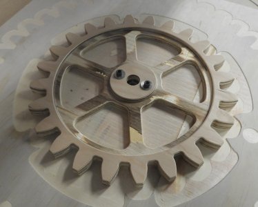
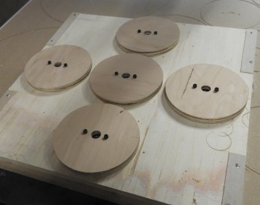
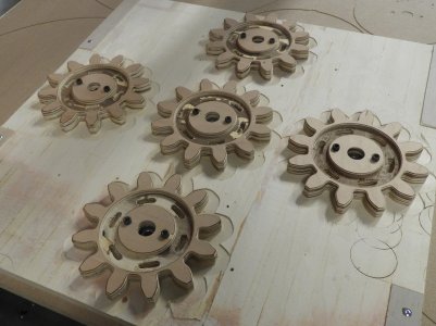
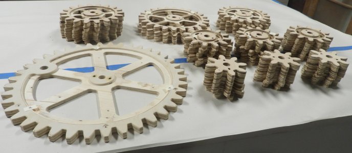
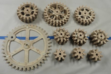
I am building a "Gear wall". All the gears are made of plywood with bearings and 3D printed mounting axils. This wall will also have light acrylic light pipes under most of the gears.

My question is this. How much should I add to the pitch diameter to ensure it spins freely? This may have over 30-45 gears in the display. I will post manufacturing pictures later when I get home. This whole display will be 96 x 60 (48, but the drive drear with handle is lower)..
 

Bandit

Super User
I have no idea! But I have never made gears from plywood, would think maybe want to take a bit off the pitch diameter to loosen things up a bit. I hope you are painting/ sealing the wood as moisture/humidity will cause swelling. Will be interesting to see, might be a grunt turning if turning 30 to 45 gears all at the same time.
 

Matt-Aburg

Ultra Member
I have no idea! But I have never made gears from plywood, would think maybe want to take a bit off the pitch diameter to loosen things up a bit. I hope you are painting/ sealing the wood as moisture/humidity will cause swelling. Will be interesting to see, might be a grunt turning if turning 30 to 45 gears all at the same time.
I meant the same thing. by adding to the pitch diameter, it will make it a bit looser. I am thinking 0.02 extra. The partner helping doing lighting will be sealing and painting also. I really am not sure yet how many will fit on the board. I manufactured 47 total, of 3, 5, 8, 13 and 21 ... pic soon....
 

PeterT

Ultra Member
Premium Member
This is just my hunch. I think on involute gears in general you want to maintain the pitch diameter to its theoretical size. If you mean account for paint finish or something I think the offset would be on the tooth itself, no? The inter-tooth fit is more a function of how close the physical tooth shape is relative to the theoretical involute curve & sufficient crest/trough clearances etc. Correctly made involute teeth roll on one another. Shape or spacing deviations introduce a degree of sliding which means friction all other things equal. Because its wood & more ornamental, probably you could space them out & may work perfectly fine if you are not really driving anything. But a long train of gears or say planetary gears, meshing & inter distance might factor. Beware of some of the download gears, I have seen some that are bogus. Supposedly Fusion-360 has actual involute forms embedded in their selectable menus.
 

Matt-Aburg

Ultra Member
This is just my hunch. I think on involute gears in general you want to maintain the pitch diameter to its theoretical size. If you mean account for paint finish or something I think the offset would be on the tooth itself, no? The inter-tooth fit is more a function of how close the physical tooth shape is relative to the theoretical involute curve & sufficient crest/trough clearances etc. Correctly made involute teeth roll on one another. Shape or spacing deviations introduce a degree of sliding which means friction all other things equal. Because its wood & more ornamental, probably you could space them out & may work perfectly fine if you are not really driving anything. But a long train of gears or say planetary gears, meshing & inter distance might factor. Beware of some of the download gears, I have seen some that are bogus. Supposedly Fusion-360 has actual involute forms embedded in their selectable menus.
These were created using a Mastercam chook. I am concerned about it being too tight. They will be sealed and stained. Also see start of assembly drawing. 1714987505169.png
 

Attachments

  • 3--5.png
    3--5.png
    37.5 KB · Views: 1
  • 5--7.png
    5--7.png
    36.4 KB · Views: 1
  • 8--10.png
    8--10.png
    39.3 KB · Views: 2
  • 13--15.png
    13--15.png
    37.9 KB · Views: 2
  • 21.png
    21.png
    38.7 KB · Views: 2

Bandit

Super User
A"crook"??
I think that gear surfaces do slide on each other in hand with rolling. I have seen many gear surfaces with wear lines running from the root of the tooth to the tip of the tooth. Some have this with a number of wavy lines running parallel to the root and tip of the tooth, or in some cases just the wavy parallel lines.
This wearing of teeth seems to be a beginning of the end, possibly caused by poor lubricant or contaminated lube, not enough lube, no extrem pressure addictives. Poor metal matches, to much clearance, causing wrong tooth loading, not enough clearance, (often worse then too much). A real killer can be too much power through a small gear train or over loading the output side, a BIG drill bit in a small drill. How far away the end is, varies. And a bunch of other things, sorry, run away there!
The fact that gears can and do work is somewhat amazing. "Well boy, just make sure a cigarette pager can be slid between them teeth". Sheesh, from the mouths of old men, ahem, I guess I am starting to be old! Can you get rolly papers any more?
How all applies to plywood gears,I am not sure. Just be sure that paper will fit tween em.LOL.
 

Matt-Aburg

Ultra Member
"Well boy, just make sure a cigarette pager can be slid between them teeth". Sheesh, from the mouths of old men, ahem, I guess I am starting to be old! Can you get rolly papers any more?
At George Brown College in 1985, the teacher told us all good machinists have rolling papers in their tool box. That made all of us good machinists because of the "smoking lounge". You could not see across the room from all the hash smoke... ahhh memories.. (c hook is an application that runs under Mastercam. This one creates gears).
 
Last edited:

Bandit

Super User
I think just having a bit of extra clearance between the gears will likely do the job, with maybe a lube of bees wax. A small hand grinder with a sanding disc/ drum for tuning any problem areas. No idea if the gears could be put on the router for a slight rework.
Extra clearance on this would not be the end of the world as the speeds are going to be low, (I think).
A lot of us are up to no good, just depends on who finds out if it matters or not!
 

Matt-Aburg

Ultra Member
I think just having a bit of extra clearance between the gears will likely do the job, with maybe a lube of bees wax. A small hand grinder with a sanding disc/ drum for tuning any problem areas. No idea if the gears could be put on the router for a slight rework.
Extra clearance on this would not be the end of the world as the speeds are going to be low, (I think).
A lot of us are up to no good, just depends on who finds out if it matters or not!
I am thinking of adding 0.01 / gear on the PD. This will mean they clear by 0.02... I will have a look on the CAD model before making this commitment to putting the axil holes in the big sheet. Today, I am running the wing off on the router. The handle on this gear is not up to date. I bought a lathe replacement handle of amazon and will update the model today. 1715096060167.png
 

Matt-Aburg

Ultra Member
Final layout into CAD.. I am machining the board main board tomorrow, and will be adding extra locators for about 5 more gears. This is front loading and so they can be added later, hopefully before the Grand opening in two weeks. We are backlighting with LED lights under all gears but the smallest 3 inch gears. The main crank will have 8 LEDS that invite people to spin, when they do, it will go off then the whole group will light up. The white tables on top of the gears are for sponsor logos. Main crank will have the Meta Makers logo.

1715364608645.png
 
Top