• Scam Alert. Members are reminded to NOT send money to buy anything. Don't buy things remote and have it shipped - go get it yourself, pay in person, and take your equipment with you. Scammers have burned people on this forum. Urgency, secrecy, excuses, selling for friend, newish members, FUD, are RED FLAGS. A video conference call is not adequate assurance. Face to face interactions are required. Please report suspicions to the forum admins. Stay Safe - anyone can get scammed.

G-Code examples

Chipper5783

Super User
That's fascinating. For full disclosure I am a CAM newbie (kindergarten level) so the idea of writing the G-code for something other than a straight line move is beyond me.
I'd be very interested in seeing an example of a 2D shape you've milled and its corresponding G-code.

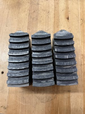
I'll share the example of the scroll teeth on the back of 3J chuck jaws. Understanding the details of math and what those teeth are accomplishing is a project all in itself (at least it was for me). Obviously one has to sort that out first - I don't see CNC as magic, you still have to know what you want and be able to describe it. The approach is well written up by Harold Hall (Google his site, he has lots of interesting projects and ideas http://www.homews.co.uk/page99a.html ).

Here is the G code that I used. I have edited out most of the embedded comments (I put a lot of comments in to explain to myself what I am doing, if I do this job again, I'll have long forgotten what I did or was thinking). The actual operation is repeated 8 times, so I have also edited out the repeats (it is simply the same call over and over again). I did this project ~5 years ago, were I to do it again I would do it differently (thinking that I have learned a few things since then) - the basic function of helical interpolation would be the same. For example I would make greater use of variables instead of editing numbers all the way down for each jaw.

In summary, the tooth shape is generated by operations called in the macros (#1 for roughing, #2 for finishing. I think it was the same type of tool, but I used a new end mill just to do a final little clean up). Then for each tooth I am shifting the referenced origin by 1/3rd of the face scroll pitch - in this case I was actually editing the G97 line ("Translation") depending on what jaw I was making (1, 2 or 3). Obviously there would be a number of approaches (you could make the jaws all exactly the same and then cut them off later - since they get trimmed anyway when setting them up on the chuck.

You can appreciate that to make this work, like any machining project, what I am sharing here is only one step - cutting the teeth into the jaw blanks. Setting the part position (machine origin), also machining all the other features of the jaws (I chose to make them as two piece jaws, but I really doubt I'll have separate the tops and the master - the whole jaw is a soft jaw and I made two sets - but that is okay, I could separate them if I felt like it some day), and setting the jaws up in the actual 3J chuck (how to put load on the jaws, trimming the ID/OD etc) - those are all separate topics or projects themselves.

Anyway, to answer your question, here is the code to cut the scroll teeth. To summarize, I am putting the tool into a starting position, then cut G13, then reposition the tool, then cut G12 - repeat. The real content is only 4 lines of code.


#1 ; Set up part program to rough cut both surfaces of each tooth. Origin backed up 0.0025
G1 R3.2778 I0.0 J0.0 A340.0 Z-0.180 F10.0 ; Positioning.
G13 R3.2222 A40.0 F1.4 ; To cut slot change to F0.5
G1 R4.6702 I-1.4385 J0.0 A15.0 Z-0.180 F10.0 ; Positioning.
G12 R4.7118 A30.0 F3.0 ; Change to F0.5 to clean up slot
$ ;

#2 ; Now finish both sides and the bottom. Climb milling
G1 R4.7118 I-1.4335 J0.0 A345.0 Z-0.193 F10.0 ; Positioning
G13 R4.6702 A30.0 F5.0 ;
G1 R3.2222 I0.0 J0.0 A20.0 F10.0 ; Positioning
G12 R3.2778 A40.0 F5.0 ;
$ ;

N200 T2 M6;
G90 G0 X3.1 Y-1.0 Z0.1 S2200 M3; Rapid to near the origin point


G97 X-0.1642; Translate for a rough cut #1, 0.0025 or 0.1692 or -0.1642
; leave 0.0025" to skim on each side of the slot.
=#1 ; Cut the first groove

G97 X0.3358; Translate for a rough cut #2, 0.5025, 0.6692 or 0.3358
=#1 ; Cut the second groove
.
.
.


; Change tool for the finishing cuts - now climb mill, both sides 0.0025"
; Add 0.1667", then -0.1667" for the next two jaws.
N300 T3 M6 ; Change tool
G90 G0 X3.1 Y-1.1 Z0.5 S2590 M3 ; Restart

G97 X-0.1667 ; Translate for finish cuts,0.0 or +-0.1667
=#2 ; Clean up the first groove

G97 X0.3333; Translate for a finish cut, 0.5, 0.6667 or 0.3333
=#2 ; Cut the second groove

G97 X0.8333; Translate for a finish cut, 1.0, 1.1667 or 0.8333
=#2 ; Cut the 3rd groove
.
.
.

M02; Program end
 

Attachments

  • image0 (1).jpeg
    image0 (1).jpeg
    769.4 KB · Views: 1
Last edited by a moderator:
Perhaps this merits a new thread?
I'll share the example of the scroll teeth on the back of 3J chuck jaws. Understanding the details of math and what those teeth are accomplishing is a project all in itself (at least it was for me). Obviously one has to sort that out first - I don't see CNC as magic, you still have to know what you want and be able to describe it. The approach is well written up by Harold Hall (Google his site, he has lots of interesting projects and ideas http://www.homews.co.uk/page99a.html ).

Here is the G code that I used. I have edited out most of the embedded comments (I put a lot of comments in to explain to myself what I am doing, if I do this job again, I'll have long forgotten what I did or was thinking). The actual operation is repeated 8 times, so I have also edited out the repeats (it is simply the same call over and over again). I did this project ~5 years ago, were I to do it again I would do it differently (thinking that I have learned a few things since then) - the basic function of helical interpolation would be the same. For example I would make greater use of variables instead of editing numbers all the way down for each jaw.

In summary, the tooth shape is generated by operations called in the macros (#1 for roughing, #2 for finishing. I think it was the same type of tool, but I used a new end mill just to do a final little clean up). Then for each tooth I am shifting the referenced origin by 1/3rd of the face scroll pitch - in this case I was actually editing the G97 line ("Translation") depending on what jaw I was making (1, 2 or 3). Obviously there would be a number of approaches (you could make the jaws all exactly the same and then cut them off later - since they get trimmed anyway when setting them up on the chuck.

You can appreciate that to make this work, like any machining project, what I am sharing here is only one step - cutting the teeth into the jaw blanks. Setting the part position (machine origin), also machining all the other features of the jaws (I chose to make them as two piece jaws, but I really doubt I'll have separate the tops and the master - the whole jaw is a soft jaw and I made two sets - but that is okay, I could separate them if I felt like it some day), and setting the jaws up in the actual 3J chuck (how to put load on the jaws, trimming the ID/OD etc) - those are all separate topics or projects themselves.

Anyway, to answer your question, here is the code to cut the scroll teeth. To summarize, I am putting the tool into a starting position, then cut G13, then reposition the tool, then cut G12 - repeat. The real content is only 4 lines of code.


#1 ; Set up part program to rough cut both surfaces of each tooth. Origin backed up 0.0025
G1 R3.2778 I0.0 J0.0 A340.0 Z-0.180 F10.0 ; Positioning.
G13 R3.2222 A40.0 F1.4 ; To cut slot change to F0.5
G1 R4.6702 I-1.4385 J0.0 A15.0 Z-0.180 F10.0 ; Positioning.
G12 R4.7118 A30.0 F3.0 ; Change to F0.5 to clean up slot
$ ;

#2 ; Now finish both sides and the bottom. Climb milling
G1 R4.7118 I-1.4335 J0.0 A345.0 Z-0.193 F10.0 ; Positioning
G13 R4.6702 A30.0 F5.0 ;
G1 R3.2222 I0.0 J0.0 A20.0 F10.0 ; Positioning
G12 R3.2778 A40.0 F5.0 ;
$ ;

N200 T2 M6;
G90 G0 X3.1 Y-1.0 Z0.1 S2200 M3; Rapid to near the origin point


G97 X-0.1642; Translate for a rough cut #1, 0.0025 or 0.1692 or -0.1642
; leave 0.0025" to skim on each side of the slot.
=#1 ; Cut the first groove

G97 X0.3358; Translate for a rough cut #2, 0.5025, 0.6692 or 0.3358
=#1 ; Cut the second groove
.
.
.


; Change tool for the finishing cuts - now climb mill, both sides 0.0025"
; Add 0.1667", then -0.1667" for the next two jaws.
N300 T3 M6 ; Change tool
G90 G0 X3.1 Y-1.1 Z0.5 S2590 M3 ; Restart

G97 X-0.1667 ; Translate for finish cuts,0.0 or +-0.1667
=#2 ; Clean up the first groove

G97 X0.3333; Translate for a finish cut, 0.5, 0.6667 or 0.3333
=#2 ; Cut the second groove

G97 X0.8333; Translate for a finish cut, 1.0, 1.1667 or 0.8333
=#2 ; Cut the 3rd groove
.
.
.

M02; Program end
One point that is often ignored is that there are many flavours of GCode. Yes, there is a standard (RS-274) but every vendor has enhanced the basics with additional features including more commands, named variables, parameters to subroutines, trig functions and and and.
 
Last edited by a moderator:
Learning how to craft your own G-code is a skill that is worthwhile in my opinion, even if you are using CAM software to create it most of the time. I've found it much easier at times to simply go in and edit the code dumped from Fusion than to go back to Fusion to repost the file, depending on what I need changed. Knowing what you are looking at is made easier by knowing how to create it.
I also crafted a basic g-code program to cut gear teeth on a 4-th axis with gear cutters. Can see if I can dig that up if of interest to anyone.
As for machine specific G-code - wouldn't know as all I've ever played with is Linuxcnc, some 3D printer stuff (GRBL) and now PathPilot (Linuxcnc under the skin), but for the most part my guess is knowing the basics of RS-274 will get you 95% of the way there, even for specific machines.
 
Caution is advised. I haven't used this in 4 years and I MAY have edited it on the fly when I last used it and didn't update my stored copy!
I just made a few editorial additions to it where I could to hopefully have it explain itself. Also, not sure about the way I formatted the equations but I was probably frustrated and just put everything in its own set of square brackets (I am not a programmer - furthest thing from one...)
But its an example of what you can do with a little knowledge. You know what they say, a little knowledge is a dangerous thing.... (be better if I had more!)
 

Attachments

Caution is advised. I haven't used this in 4 years and I MAY have edited it on the fly when I last used it and didn't update my stored copy!
I just made a few editorial additions to it where I could to hopefully have it explain itself. Also, not sure about the way I formatted the equations but I was probably frustrated and just put everything in its own set of square brackets (I am not a programmer - furthest thing from one...)
But its an example of what you can do with a little knowledge. You know what they say, a little knowledge is a dangerous thing.... (be better if I had more!)
My first job in software was programming HP pen plotters. It was, of course, using a proprietary HP "g-code". And when you crash the pen plotters you only scribble over other line...
 
If you are interested in a REALLY beginner start at G-Code, the way we teach it to our students is using a first example of engraving their name on a flat plate. Basically using G00-G01-G02-G03 for starters and using very basic letter-number shapes as below: each point is 0.125 apart.

1731630176785.png
 
One point that is often ignored is that there are many flavours of GCode. Yes, there is a standard (RS-274) but every vendor has enhanced the basics with additional features including more commands, named variables, parameters to subroutines, trig functions and and and.
Yes, my mill is Bridgeport VMC using DX32, the lathe is Cincinnati Falcon using Acramatic A2100. I think of them as being dialects of G Code (still G Code). Coding direct is working quite well for me for what I use the machines for.
 
Last edited:
One thing to keep in mind if your thinking of making the jump to CNC, is that you can start with really simple commands that just replicate what you would do manually; G0, G1 etc. then try putting those simple sequences into subroutines that you can call again and again. 90% of what I do is really simple stuff. Let's you vacuum the chips while the machine dutifully does what it's told to do. I make plenty of really simple 20 or less line programs it's just way less likely I will make a mistake.

For example today I needed to drill quite a few deep 1/8" holes in a line in aluminum. Very simple program just pecking then rising quickly to clear the bit, and then down fast to the previous depth and then slow for another peck. Just a lot of boring repetition that is better done by a machine.
 
For an example of some of the non-standard GCode features in LinuxCNC see the program below. It uses named variables, system variables, debug output, arithmetic, while loops, math functions and other goodies. The project was to use my CNC to broach the ribs for clone Multifix tool holders. You can see a video of it in action at

(Broaching Routine)
(Mon Aug 9, 2021)

(parameters for Multifix holder)
#<curveDiameter> = 1.236
#<curveRadius> = [#<curveDiameter> / 2]
(debug, curveDiameter = #<curveDiameter>, curveRadius = #<curveRadius>)
#<grooveDeep> = 0.040
#<Ztop> = .2
#<Zbottom> = -0.85

#<angleStart> = -49.5
#<angleFinish> = -#<angleStart>

#<Xcentre> = 0.0
#<Ycentre> = 0.0
#<Zcentre> = 0.0

(variables used to control broaching)
#<broachTool> = 601

;safety setup
G20 ;use inches for length units
G17 ;XY plane select
G90 ;absolute distance mode
G40 ;turn cutter compensation off
G49 ;cancels tool length compensation
G80 ;turn canned cycle off
G91.1 ;incremental distance mode for I,J&K offsets
G94 ;feed is Units per Minute Mode

;Initial tool setup
M09 ;Coolant OFF
M05 ;Spindle OFF
G30 ;go to tool change position

T#<broachTool> M6 ;change the tool
G43 ;apply offsets
#<toolDiameter> = #5410
#<toolRadius> = [#<toolDiameter>/2]

(debug, Xcentre = #<Xcentre>, curveRadius = #<curveRadius>, toolRadius = #<toolRadius>)

#<minX> = [#<Xcentre> + [#<curveRadius> - #<toolRadius>]]

(debug,Calculated minX = #<minX>)
#<maxX> = [#<minX> + [#<grooveDeep>]]
#<advanceX> = 0.002
(calculate number of strokes)
#<strokes> = [FUP[#<grooveDeep> / #<advanceX>]]
#<advanceX> = [[#<grooveDeep>] / #<strokes>]


#<minY> = #<Ycentre>
#<maxY> = #<minY>
#<advanceY> = 0.05

#<minA> = #<angleStart>
#<maxA> = #<angleFinish>
#<advanceA> = 9
#<backlash> = 2

(debug,Broach diameters = #<toolDiameter>, radius = #<toolRadius>)
(debug,Start broach at X = #<minX>, Depth = #<grooveDeep>, Strokes = #<strokes> Step = #<advanceX>, A = #<minA>)

#<retractX> = 0.05
#<feedRate> = 100
F #<feedRate>
G01 Y#<minY>
G01 X#<minX>

#<currA> = #<minA>

o601 while [#<currA> LE #<maxA>]
G01 Z#<Ztop>
G00 A[#<currA> - #<backlash>] ; backlash elimination (approach from same side)
G00 A#<currA>

#<currX> = #<minX>
o501 while [#<currX> LE #<maxX>]
(debug,Stroke A = #<currA>, X = #<currX>)

G00 Z#<Ztop> ; position at top of stroke
G00 X#<currX> ; position for stroke
G01 Z#<Zbottom> ; and stroke to bottom
G00 X[#<currX> - #<retractX>]; retract from the work

#<currX> = [#<currX> + #<advanceX>]

o501 endwhile

#<currA> = [#<currA> + #<advanceA>]
o601 endwhile

; Done broaching so move to good position
G00 Y#<minY>
G00 X#<minX>
G00 Z#<Ztop>
G00 A0


;FOOTER
M09 ;Coolant OFF
G30
M30
%
 
Last edited:
My first job in software was programming HP pen plotters. It was, of course, using a proprietary HP "g-code". And when you crash the pen plotters you only scribble over other line...

What a great trip down memory lane. I spent quite a while creating custom plots to identify hot spots to locate car dealerships based on demographics, sales data, and provincial licensing records. The result was both positive and negative hot spots for potential dealerships on maps of the USA and Canada and also high density regional and municipal areas. The pen colours on the plotter allowed everyone to see the best locations for new dealerships as well as the worst places. The latter was particularly interesting and resulted in a number of closures. I doubt they do it that way today, but it was ground breaking work at the time.
 
Back
Top