deleted_user
Super User
David_R8 commented on something I had posted on another thread so I thought maybe others may be interested in this long term project I am working on.
So far I am mostly in the design phase and have a few issues to work out and materials to source before I get going in earnest.
Preamble (skip if desired):
I wanted to take my dogs along on hikes on old rail trails around Ontario. We tried it a few times and they just can't go very far with the heat and their short little shih tzu legs. So next I figured I'd bike those trails and take the dogs along in a bike trailer. They did not enjoy this. It surmised that it was both too bouncy and they did not like trailing behind., frankly they like to blaze the trail and see where we're headed.
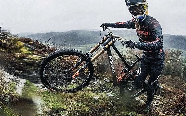
I've also always wanted to own a board track racer but my budget doesn't allow that. I'm on another forum where people often post about constructing custom bike frames. I thought that if they could do it I surely could as well. During my research I stumbled across an early 1900s photo of a dog in a sidecar attached to a Harley. The idea was born to add the sidecar build to the project and revisit the idea of rail trailing with my dogs.
![AM-JKLU6KNTxNiG7hUXS67D_rrQtlOm1GS8qKaq_0mRiURE_tr9kf_ZudYex1pepZ4OKdr27Vdc-K6ttqdPQilVDf5qcseEDhcTmwE6eR91ynO6hQyMR_hc0-A8eCOreJoPWRlPSTkuPEFEyLrluy4OsDUem=w1037-h531-no]()

The design criteria
In order to use both Toronto bike paths and most rail trails I'd have to design a pedelec, which is a ebike with pedal sensors that provide feedback on how much power the motor should output to assist the rider. I'd have to be able to convince any authorities that the output was within the required kW rating, which meant that there must not be a throttle on the bike in such usage. I'd use VESC based software controls and a cycle computer (Cycle Analyst) to limit motor output to meet Ontario regulations (with a little cheating for hill climbing because I have many hills near me).
The cycle analyst allows me to easily add a throttle to the bike if I wanted to convert to motor cycle for use where allowed such as on a private track. Since I wanted a board track racer I wanted a motor capable of board track racer speeds IF I desired. I performed a series of calculations and determined that I'd want a motor capable of 4kW continuous output, even if my initial speed controller and battery were not capable of operating at the required amperage.
I settled for an initial continuous operating current of 25 amps for all components in the system. With that design current and a phaserunner controller from Grin tech (90v, 96 peak amps) I can output ~2kW with a 72 volt battery pack. More than enough power to push me, my bike, sidecar and two small dogs all day long.
That's when I started researching what makes the best proven reliable and powerful DC motor designs. I then tried to take elements from each to design my own motor that I hope can output close to 4kW. Time will tell.
One remarkable motor design, the Lynch motor, was developed by from someone without any previous knowledge in motor design. When first developed it was exclusively a brushed DC motor of and axial design. Over the past 25 years the technology was improved upon and the IP was bought and sold a few times. Briggs and Stratton acquired the rights and sold the motors as Etek Motors, they were powerful better replacements for the 6HP gas motors that were Brigg's bread and butter. Needless to say they hindered market development for a long time. It is both the axial design and the unique very robust stator coil design that I wanted from this motor.
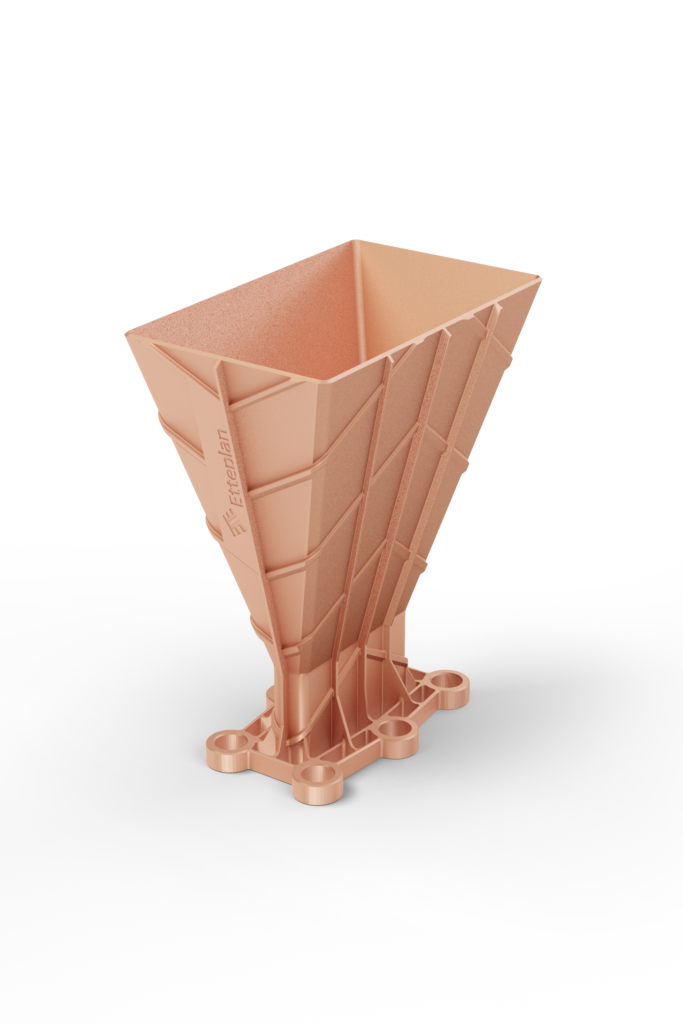
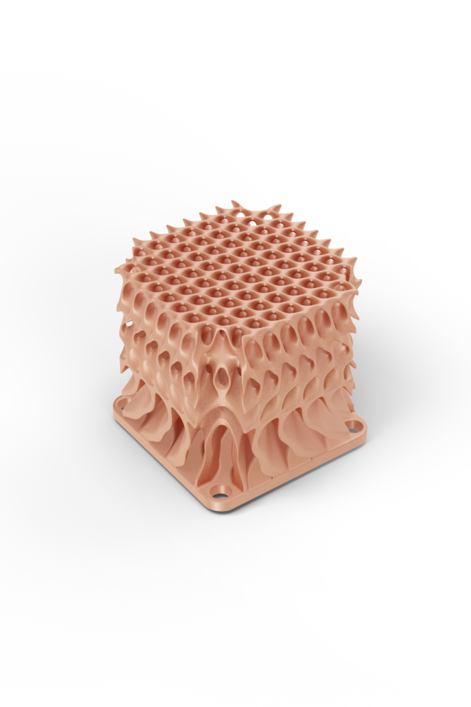
Another design element I wanted for my motor was modularity to ease the construction. I also toyed with the idea of Binding Jetting copper printing, except I could not find anyone in Canada that offered binder jet service for copper. The prices from foreign firm was in the many thousands of dollars. Their target market is really more for parts like these:
![Bullhorn-Antenna-683x1024.png]()
![Diamond_4-683x1024.png]()
My Stator coils are more like this:

The illustration below shows the copper stator elements coloured to show the phase winding scheme more clearly. The image also shows the stator core, one of the two rotor hubs, and the splined end of the motor spindle.

The above image shows one things I've done that is unique, which is to put the bike's cranks thru the motor spindle. At the time I thought of this concept I did not think that it had been done before but I discovered a German company (Binova) had indeed done so on a rare ebike conversion kit they'd designed.
It made excellent use of modular construction as well, in fact superior to the best motors I'd seen designed for EV automobiles.
I am making jigs to assemble the motor stator and to cast the stator in resin. This process will also affix the stator to the stator hub on the interior side and the aluminum cooling and mounting ring on the exterior. A cooling loop of copper tubing will also be cast in place for the oil cooling system that will keep the stator under 155 deg C.
I'm also using 3d printed jigs to build the motor's rotors with their magnet arrays. Well actually I will try to make an entirely 3d printed rotor except for the back iron rings and and exterior metal ring to reinforce the rotor's perimeter, and of course the keyless hub that affixes the rotors to the spindle. The idea is to lighten the rotor and provide precise location of the magnet array.


Below shows the set of spacers that help align and epoxy the magnets in place. They then get removed and the voids filled with epoxy.

IF the 3D printed parts are not robust enough (carbon fiber reinforced filaments) I'll try to "forged carbon fiber" casting process to make rotors. But I am hopeful that the 3D will work sufficiently well.
below shows where I'm tucking in the cooling tubes between the stator and the exterior mounting ring

Below shows the gates belt cog from the motor to the rear 3 speed hub. The crank side also uses gates belt drive. the driveline lengths are equal in order to ensure that tensioning is not complicated. The drive ratios have also been carefully calculated to ensure all operating ranges are covered well. I nixed a CVT hub idea because they can't handle the input torque output by the motor.

More to come if people are interested.
I do have issues to solve I'd like input on.
One:
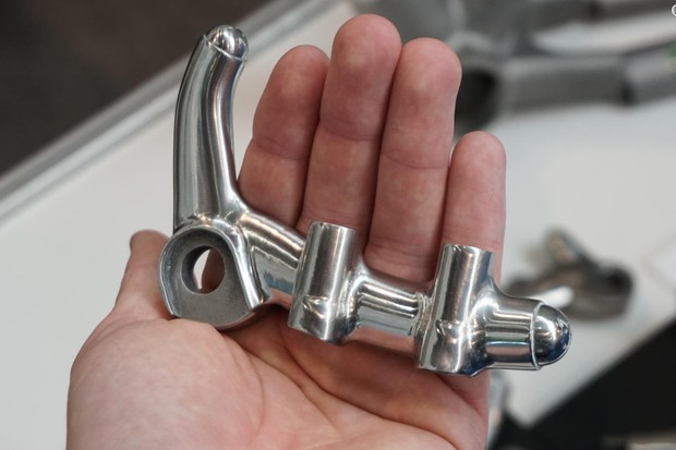
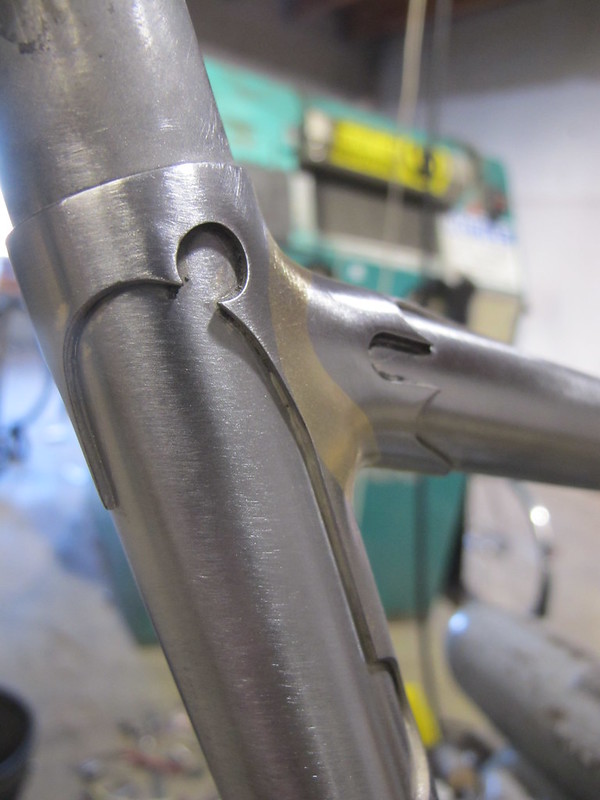
How to make steel lugs to use to reinforce and braze the tubing together in the period style. Typically these are investment cast. These don't match any of those cast items found at bike parts suppliers. I supposed I can appeal to CNC mill owners to machine me a set from design I supply. Or I can try to investment cast using an a lower melting point alloy... any ideas of suitable replacement? That would require a major investment on my part. See, I can do puns.
Two:
How to manufacture about 100 copper coil elements from sheet copper. Initially I was going to use a die punch for this, but when I inquired with a few edm shops none responded to my request for price to machine my die and punch. They must be busy with real customers. My mill is not really suitable for making these parts. But mybe someone with a cnc mill would want to help out?
The dies I have designed for the stator coil elements:

I also need stamped copper plates to make the electrical contacts in a compression type battery pack I am building for other ebikes I am building.
The other option is having the parts cut on a cnc router. Again something I lack... anyone want to help out here?
The battery contact plates, I already 3D printed the stamping moulds to emboss the contact points. I just need cnc router or die set made to punch these too.

I really want to make as many parts for this project as possible, so I may tackle building a rear hub too.
So far I am mostly in the design phase and have a few issues to work out and materials to source before I get going in earnest.
Preamble (skip if desired):
I wanted to take my dogs along on hikes on old rail trails around Ontario. We tried it a few times and they just can't go very far with the heat and their short little shih tzu legs. So next I figured I'd bike those trails and take the dogs along in a bike trailer. They did not enjoy this. It surmised that it was both too bouncy and they did not like trailing behind., frankly they like to blaze the trail and see where we're headed.
I've also always wanted to own a board track racer but my budget doesn't allow that. I'm on another forum where people often post about constructing custom bike frames. I thought that if they could do it I surely could as well. During my research I stumbled across an early 1900s photo of a dog in a sidecar attached to a Harley. The idea was born to add the sidecar build to the project and revisit the idea of rail trailing with my dogs.

The design criteria
In order to use both Toronto bike paths and most rail trails I'd have to design a pedelec, which is a ebike with pedal sensors that provide feedback on how much power the motor should output to assist the rider. I'd have to be able to convince any authorities that the output was within the required kW rating, which meant that there must not be a throttle on the bike in such usage. I'd use VESC based software controls and a cycle computer (Cycle Analyst) to limit motor output to meet Ontario regulations (with a little cheating for hill climbing because I have many hills near me).
The cycle analyst allows me to easily add a throttle to the bike if I wanted to convert to motor cycle for use where allowed such as on a private track. Since I wanted a board track racer I wanted a motor capable of board track racer speeds IF I desired. I performed a series of calculations and determined that I'd want a motor capable of 4kW continuous output, even if my initial speed controller and battery were not capable of operating at the required amperage.
I settled for an initial continuous operating current of 25 amps for all components in the system. With that design current and a phaserunner controller from Grin tech (90v, 96 peak amps) I can output ~2kW with a 72 volt battery pack. More than enough power to push me, my bike, sidecar and two small dogs all day long.
That's when I started researching what makes the best proven reliable and powerful DC motor designs. I then tried to take elements from each to design my own motor that I hope can output close to 4kW. Time will tell.
One remarkable motor design, the Lynch motor, was developed by from someone without any previous knowledge in motor design. When first developed it was exclusively a brushed DC motor of and axial design. Over the past 25 years the technology was improved upon and the IP was bought and sold a few times. Briggs and Stratton acquired the rights and sold the motors as Etek Motors, they were powerful better replacements for the 6HP gas motors that were Brigg's bread and butter. Needless to say they hindered market development for a long time. It is both the axial design and the unique very robust stator coil design that I wanted from this motor.
Another design element I wanted for my motor was modularity to ease the construction. I also toyed with the idea of Binding Jetting copper printing, except I could not find anyone in Canada that offered binder jet service for copper. The prices from foreign firm was in the many thousands of dollars. Their target market is really more for parts like these:
My Stator coils are more like this:

The illustration below shows the copper stator elements coloured to show the phase winding scheme more clearly. The image also shows the stator core, one of the two rotor hubs, and the splined end of the motor spindle.

The above image shows one things I've done that is unique, which is to put the bike's cranks thru the motor spindle. At the time I thought of this concept I did not think that it had been done before but I discovered a German company (Binova) had indeed done so on a rare ebike conversion kit they'd designed.
It made excellent use of modular construction as well, in fact superior to the best motors I'd seen designed for EV automobiles.
I am making jigs to assemble the motor stator and to cast the stator in resin. This process will also affix the stator to the stator hub on the interior side and the aluminum cooling and mounting ring on the exterior. A cooling loop of copper tubing will also be cast in place for the oil cooling system that will keep the stator under 155 deg C.
I'm also using 3d printed jigs to build the motor's rotors with their magnet arrays. Well actually I will try to make an entirely 3d printed rotor except for the back iron rings and and exterior metal ring to reinforce the rotor's perimeter, and of course the keyless hub that affixes the rotors to the spindle. The idea is to lighten the rotor and provide precise location of the magnet array.


Below shows the set of spacers that help align and epoxy the magnets in place. They then get removed and the voids filled with epoxy.

IF the 3D printed parts are not robust enough (carbon fiber reinforced filaments) I'll try to "forged carbon fiber" casting process to make rotors. But I am hopeful that the 3D will work sufficiently well.
below shows where I'm tucking in the cooling tubes between the stator and the exterior mounting ring

Below shows the gates belt cog from the motor to the rear 3 speed hub. The crank side also uses gates belt drive. the driveline lengths are equal in order to ensure that tensioning is not complicated. The drive ratios have also been carefully calculated to ensure all operating ranges are covered well. I nixed a CVT hub idea because they can't handle the input torque output by the motor.

More to come if people are interested.
I do have issues to solve I'd like input on.
One:
How to make steel lugs to use to reinforce and braze the tubing together in the period style. Typically these are investment cast. These don't match any of those cast items found at bike parts suppliers. I supposed I can appeal to CNC mill owners to machine me a set from design I supply. Or I can try to investment cast using an a lower melting point alloy... any ideas of suitable replacement? That would require a major investment on my part. See, I can do puns.
Two:
How to manufacture about 100 copper coil elements from sheet copper. Initially I was going to use a die punch for this, but when I inquired with a few edm shops none responded to my request for price to machine my die and punch. They must be busy with real customers. My mill is not really suitable for making these parts. But mybe someone with a cnc mill would want to help out?
The dies I have designed for the stator coil elements:

I also need stamped copper plates to make the electrical contacts in a compression type battery pack I am building for other ebikes I am building.
The other option is having the parts cut on a cnc router. Again something I lack... anyone want to help out here?
The battery contact plates, I already 3D printed the stamping moulds to emboss the contact points. I just need cnc router or die set made to punch these too.

I really want to make as many parts for this project as possible, so I may tackle building a rear hub too.