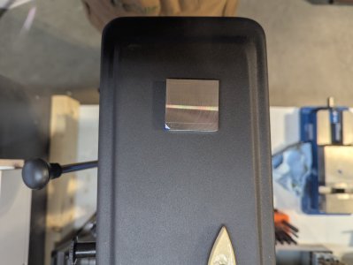
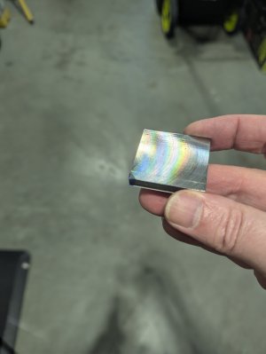
Hey folks, looking for a little insight. I finally got a descent fly cutter working on my King VS15. The leading edge leaves a great finish, but when the trailing edge comes in contact, it starts to gouge. I checked the mill setup and it's within .001 which is terrific for this mill. See pics and thanks for the help. Cheers
-
Scam Alert. Members are reminded to NOT send money to buy anything. Don't buy things remote and have it shipped - go get it yourself, pay in person, and take your equipment with you. Scammers have burned people on this forum. Urgency, secrecy, excuses, selling for friend, newish members, FUD, are RED FLAGS. A video conference call is not adequate assurance. Face to face interactions are required. Please report suspicions to the forum admins. Stay Safe - anyone can get scammed.
-
Several Regions have held meetups already, but others are being planned or are evaluating the interest. The Calgary Area Meetup is set for Saturday July 12th at 10am. The signup thread is here! Arbutus has also explored interest in a Fraser Valley meetup but it seems members either missed his thread or had other plans. Let him know if you are interested in a meetup later in the year by posting here! Slowpoke is trying to pull together an Ottawa area meetup later this summer. No date has been selected yet, so let him know if you are interested here! We are not aware of any other meetups being planned this year. If you are interested in doing something in your area, let everyone know and make it happen! Meetups are a great way to make new machining friends and get hands on help in your area. Don’t be shy, sign up and come, or plan your own meetup!
You are using an out of date browser. It may not display this or other websites correctly.
You should upgrade or use an alternative browser.
You should upgrade or use an alternative browser.
Fly Cutter Issue
- Thread starter Feeop
- Start date
89.98 degrees is about as close as I can get itSo the left to right tilt is within a thou?
From my experience, I think your gouges are caused by swarf. A little continuous compressed air to blow away the swarf should solve that problem.
If swarf is not continuously blown away, it can get trapped under the edge and gouge the surface.
If swarf is not continuously blown away, it can get trapped under the edge and gouge the surface.
I'll check that tomorrow. ThxOk but have you checked the tram of the spindle to the mill table?
Agree with Susquatch, looks like something may be loose or not rigid. Reduce the stickout of fly cutter as much as possible. Tighten up the ways a tad bit more.
When you say fly cutter, are we talking single point HSS tool type? Tool ground properly?
Too large of tip radius can cause chatter.
"
Point Radius
Professional machinists maintain the point radius of the fly cutter tool to less than 1.5mm. This is because the smaller the point radius, the slower the feed rate, thus giving a fine finish. Thus, make you avoid large tip radiuses as they increase the tool cutting pressure, causing deflections. This eventually results in squealing, chatters, and poor finishing outcomes.
"
When I use a single point flycutter I prefer to have the tram slightly out. (I'm not sure if this is right). The leading edge of the cut is very clean. The trailing edge cut is just brushing the surface. Maybe try working in the direction of the low side of your tram.
Just a few amatuer thoughts. cheers, P.
When I use a single point flycutter I prefer to have the tram slightly out. (I'm not sure if this is right). The leading edge of the cut is very clean. The trailing edge cut is just brushing the surface. Maybe try working in the direction of the low side of your tram.
I think this works better when using a face mill. I've never had to do that with a fly cutter. But still, it's worth playing with. The chatter is clear evidence that the cutter is trying to cut when it shouldn't.
How does the cut look going the other way?
Maybe the front cut is stressed too much which is raising the cut leaving material behind so the trailing swipe is still cutting. Raising the back side of the cut a bit might fix that. Might be a simple tram problem. Again, how does the cut look going the other way?
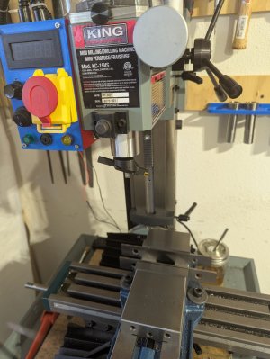
@Feeop - The other thing that has occurred to me is that the fly cutter might simply be too big for the mill. Can you post a photo of the whole setup so we can get a sense of the scale we are dealing with here?
Also speed, depth of cut for the tool, etc.
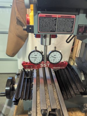
Well I think I have found the culprit (and I can't believe I forgot I had this tool). It would appear that the bed is out +.007 on the Y axis to the front (bang on for the X axis). This would seem to make sense since the gouge was in the front left corner of the piece I was working on.
Now, how do I fix that???
The pics show the gauge and fly cutter setup I was using.
Thanks again
Now, how do I fix that???
The pics show the gauge and fly cutter setup I was using.
Thanks again
Attachments
I believe that adjusting nod on your Mill is done with shims under the head bolts. But it may also be done with shims under the column. Helps to have two sets of shims to do this. I'd just use feeler gauge blades till you know what you need. Then make a proper shim for it.
If you just happen to have a flat plate (a brake disk is ideal), to run the indicators on, it will make the job easier to do cuz you won't have to deal with the T-slots. It will also extend the table to improve accuracy.
It can be a bit of a challenge to work out how much does what. I found that making a drawing of the geometry significantly helped get the adjustments close much faster than stabbing around in the dark.
Improper nod should have just cut a front to back taper so I'm not convinced that nod explains everything. But you have to fix that first, so let's see what happens after you do.