• Scam Alert. Members are reminded to NOT send money to buy anything. Don't buy things remote and have it shipped - go get it yourself, pay in person, and take your equipment with you. Scammers have burned people on this forum. Urgency, secrecy, excuses, selling for friend, newish members, FUD, are RED FLAGS. A video conference call is not adequate assurance. Face to face interactions are required. Please report suspicions to the forum admins. Stay Safe - anyone can get scammed.

Fabricated Fixture plate

Dan Dubeau

Ultra Member
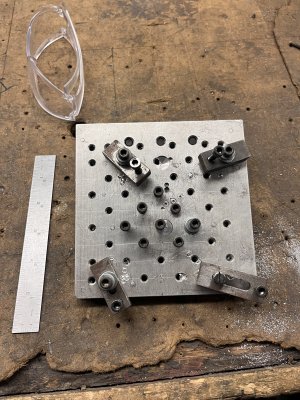
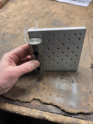
Here a fixture plate I made today. I've had this Idea rolling around in my head for probably a decade, and finally had enough of a need for it that I built it. Nobody likes taking a vise off for a quick plate job, so the idea behind this is to have a "flat surface" I can toss in a vise whenever I need to do some "2d" work on a plate/flat part. A bunch of hold down holes, and enough of a ledge all the way around I can use a clamp whatever I need to hold. I sized this one to be used with both the 6" vise on my Manual mill, and the double 4" vises in the Tormach.

On with the pics......When I first thought of this idea, I was going to use 6" channel for the vise mount, but those 4" vises don't open that wide......So I found some 3" beam that I figured could work with some reinforcement. I was also going to use bolt on mic6 plates for the top, but I no longer have a never ending supply of mic6 offcuts, so that Idea was out. I used 4x7x3/8" plates instead.
Q1Ok6rU.jpeg


Quick layout to see how it looks.
7xLSXtK.jpeg


Cut some filler pieces from some 3/8" thick scrap, and milled them to the same thickness.
1UlZPz3.jpeg

c0ub0rS.jpeg

0XnYT6X.jpeg


Layed them out where they will support both visesthe best and welded them in. When I do projects like this, I like to play around with stuff. Upper one I tried to hold a steady hand, the bottom one I did small circles. Never hurts to try stuff, and see how you like it. Did some other patterns on all the other welds too. I like the steady hand the best, I just wish I had one lol.
KFnVLi1.jpeg


I let it cool down over lunch, then milled it all up square on all sides, and took it down about 0.3" in height (to 2.100"). Just high enough that a tee nut will clear the jaws on a 6" vise. Guess I didn't get any other pics of this process....
IDnC4GB.jpeg
nmgPvGl.jpeg


Once it was all squared up, I clamped up the top plates where I wanted them, using a 1.5 tube for a spacer, and welded them on the corners as I didn't want to warp the 3/8" thick plates. Also took some measurements so I could do a quick cad layout and program the holes.
eWPDhSv.jpeg

eLH4oHk.jpeg

duKO65u.jpeg

Ctyoist.jpeg


Didn't notice this until posting these pics and looking at it on the screen, but it looks like those welds didn't penetrate in the middle and you can see a crack there between the supports. Took some head scratching to figure out why, but it's because while I DID weld them across the bottom, I also took about 0.075" off that side, so that would have machined off whatever weld was there anyway...had me worried about it for a second....

Left it to cool while I made dinner, then went back out and faced it down. Was expecting to see a bit of warp here, but 0.015" cleaned it up very nicely. This was also a bit of a rigidity test here, especially on the longer overhang, and I was surprised how goo it was. Only a tiny bit of chatter is perceptible in the finish compared to the more supported parts.
ASnqkF5.jpeg


Here you can see I left the spacing at 5/8" so I can use stock tee nuts if I ever needed to. Never hurts to have options....
cmU1I5O.jpeg


I also walked an EM all around it to square the edges up.
UllaVSk.jpeg


Now it was time to jump in the Tormach for hole drilling. The thought of drilling these by hand isn't my idea of a good time.....

8tT6K14.jpeg


I was more concerned about this fitting the work envelope of the Tormach because I'll probably use it the most here for profiling stuff from plate. That is the reason I needed to finally build it right now. With the double vice setup, I don't really want to take them off more than I have to to do flat stuff.
xhjpM8n.jpeg


Spot drill
L9wDt5F.jpeg


Drill #7
I9duU5y.jpeg


While the CNC was drilling, I jumped in the lathe to face off some bolts for spacers/standoffs. I have another idea for these that I can't wait to try tomorrow. It may, or May not work, we'll see.....
uqOaNTT.jpeg

bNYiQn2.jpeg


Then edited the spot program to chamfer the holes.
DpZZwtY.jpeg


Then it was time to tap the holes. Trusty makita, a nice fresh 1/4"-20 spiral point tap, and some anchor lube. My first time using it. It's alright, did it's job I guess. I like that it stays put. I usually use rapid tap for steel, but can see anchor lube earning a spot in the lineup.
AXVCUxB.jpeg
 
Last edited:
And here's the final product. Ready for action.
iY40dQU.jpeg


Hopefully I will give it a work out tomorrow cutting some plates for my belt grinder.

This isn't, nor was it meant to be a fine reference piece of work holding here, it's a fixture/hold down plate. If I need to drill new holes to hold something down I will, if I accidentally mill/drill into it I won't lose sleep over it.....I was going to make those plates removable in case they ever got too beat up I could just swap them out, but figured I can just zip off the welds and replace if that time ever comes. At a certain point in the Imagineering process, you gotta stop adding features, and just build the damn thing....I am my own worst enemy in that regard.....
 
Thanks. They are "close". I bought them (from busy bee) with the intentions of match grinding them in all the same, and doing a bunch of other modifications to them, but they sat at work for a few months and I just never got to them before I left for another job. My grinder isn't big enough to do them (nor do I trust it to make them any better). I did map them all out on a surface plate, and while I don't remember the exact #'s now, 0.0007" seems to ring a bell as the max deviation in bed height between the two. They were pretty dang close, With one being dead flat, and the other being a few tenths thicker and having a few tenths more rise in thickness near the back. All in all, they're not that bad for the $, but they're not exactly perfect either, there's a few things I don't like about them I'll probably fix eventually (I don't like either jaws), but I think they'll be fine for my needs for now, and they certainly fit better on the Tormach than a 6" vise. A 5" would probably fit fine too, but I wanted the extra utility from a double vise setup for running multi op production stuff occasionally. Hence why I made the fixture plate, so I don't have to take them off as much.
 
Thanks. They are "close". I bought them (from busy bee) with the intentions of match grinding them in all the same, and doing a bunch of other modifications to them, but they sat at work for a few months and I just never got to them before I left for another job. My grinder isn't big enough to do them (nor do I trust it to make them any better). I did map them all out on a surface plate, and while I don't remember the exact #'s now, 0.0007" seems to ring a bell as the max deviation in bed height between the two. They were pretty dang close, With one being dead flat, and the other being a few tenths thicker and having a few tenths more rise in thickness near the back. All in all, they're not that bad for the $, but they're not exactly perfect either, there's a few things I don't like about them I'll probably fix eventually (I don't like either jaws), but I think they'll be fine for my needs for now, and they certainly fit better on the Tormach than a 6" vise. A 5" would probably fit fine too, but I wanted the extra utility from a double vise setup for running multi op production stuff occasionally. Hence why I made the fixture plate, so I don't have to take them off as much.
Thanks Dan. I'm looking at all workholding options for my CNC conversion.
 
They're not terrible, but If I were to buy over I might not go this route again. I was basically buying these as a kit, these thinking I would only end up using the bed and screw/nut. And I'd remake/refit the rest. Now I no longer have access to the tools and equipment to remake the jaws how I want, or make the bodies matched, and perfectly square all around anymore. My precision capabilities in my home shop stop at 3 decimal places lol. I'm not sure any of the other import options are any better though. Busy bee at least had a good return policy.....

In the mid tier zone, A 4, or 5" Glacern would be a better out of the box solution, but it's 3x more money, which is something to keep in mind. I have a 6" at home, and bought 2 of them for work many years ago and I think they're good quality and a great value for the money. GS/Sowa go on sale every once in a while too, and they're also pretty nice as well.

This of course is assuming that a genuine Kurt is out of the question lol. It certainly was for me.....
I loved the 4"Glacern I had on my old mill but like you say they are pretty expensive. Especially for a pair of them. I'll look at Shars as well as I can get US shipping.
Busy Bee has their 4" Acculock on sale for $90 each. Free shipping.
 
Last edited:
I have a tiny aluminum one at work, that I made after seeing the idea in Tom Lipton’s book.

IMG_6555.jpegIMG_6557.jpeg

Roughly 5” square, 1/2” thick (just an offcut). We have a few Tapmatic tapping heads at work, so the holes weren’t a pain. The strap clamps are the most work, honestly. The 1 1/4” round bar on the back is so you can clamp that in the vise, and set it at an angle (hardly a sine plate, but it works).

Mostly gets used for drilling holes in little sheet metal parts, butting them up against stops, but occasionally for other things.

My coworkers have discovered it, and it’s starting to show more wear than in its first few years…
 
I have a tiny aluminum one at work, that I made after seeing the idea in Tom Lipton’s book.

View attachment 60203View attachment 60204

Roughly 5” square, 1/2” thick (just an offcut). We have a few Tapmatic tapping heads at work, so the holes weren’t a pain. The strap clamps are the most work, honestly. The 1 1/4” round bar on the back is so you can clamp that in the vise, and set it at an angle (hardly a sine plate, but it works).

Mostly gets used for drilling holes in little sheet metal parts, butting them up against stops, but occasionally for other things.

My coworkers have discovered it, and it’s starting to show more wear than in its first few years…
Nice, I like that design. Somewhere in my stash is a 2.5"chunk of O1, and a mic6 plate I squirreled away to make one of those, but i just never got around to it. I had a lot of those projects when I cleaned up my desk/bench lol.. I've only opened the bottom drawer of my toolbox once since I brought it home and just said "urgh" and then closed it. There's a lifetime of unfinished projects just in that drawer......Another of Tom Liptons designs in there is his little vise held bender. Someday I might get to them......

I believe you on the strap clamps. Small fiddly parts like that take a lot of work. DJberta, I don't really have a plan as of yet, I can use Kant twist clamps for now, and if my other idea works, it should hold off the making of them for a while. I wouldn't mind to try making a set like this though.
clamp.jpg


I have another angle plate with a 1/4" grid of holes I made, that could benefit from a set of clamps too. And I think forging them would be a fun. project.
 
Thank you for the project write up and pictures. I really enjoy tagging along on projects and getting new ideas.
 
I wouldn't mind to try making a set like this though.
View attachment 60205

Seeing this disturbed the dust in my memory and made me ponder using some cast off rockers from an old small block Chev. Is that a crazy thought?

It would probably need some sort of a post to stand in for the pushrod but that wouldn’t be too hard to come by and the fulcrum ball would be a good pivot.

Any other rockers that would be better?

D :cool:
I had the same thought before too, but don't have any to try. I don't think they'd work without some modification, perhaps a jack screw in the tail for height adjustment, and they'd also be pretty tall. Roller rockers would better, or at least they "look" closer. I still think unless you had some sitting around for "free", you'd be better off starting from scratch with more suitable dimensions. I love repurposing stuff like that, and looking at stuff that's served it's original purpose and seeing what else it could be before sending it to the scrap pile.
 
a fixture plate I made today. I've had this Idea rolling around in my head for probably a decade
I like your build and the design. Thanks for sharing and including the details. Well done!

I have had a similar fixture plate rattling around for a couple years - but mine only made it to the drafting board. It is now getting a little closer to the top of the list. Your post moved it up a couple spots in the queue.

My fixture plate could be used on the mill but primarily would be for welding/fabricating. On the mill it would be clamped to the table to hold a long part (a trade-off, move the vise vs gain rigidity). It would also have an attachment for one end that would hold a vertical component to make it work like a very large angle plate (brace for welding components at 90 degrees). The top surface would be 8.5" wide and about 24" long (bigger is better, but I don't want it to exceed 45 pounds.

Anyhow - my big take-away from your design is that your top surface components (slats) and the T slots are transverse (in the Y direction). My design (gathering dust on the board) was to have 2 longitudinal T slots (in the X direction). It had three longitudinal slats of 2.5" x 3/8" cold rolled and would be 8.5" wide (which includes two 1/2" T slots). So don't be surprised if your idea gets stollen and I build using transverse slats. 8-) Well back to the drafting table.

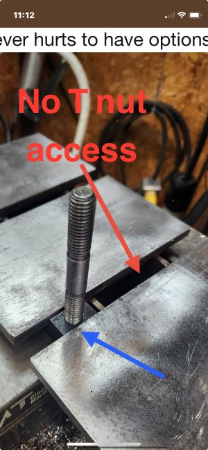
Your pictures also got me thinking about the T nuts. I had thought that I would need to have a spacer between the frame and the slats so that the T nuts could slide unobstructed. But my design had 24" long T slots vs your relatively short transverse T slots. I also noticed (in your design) that you have way more taped hole (for hold down bar clamp studs) than I had planned. I like that approach (thanks) since it improves versatility and makes the T slots less important. One minor issue with your design (as I understand it from your pictures) is that the T slots are not continuous and you cannot install a T nut in the centre portion, see marked-up screenshot pic:
IMG_3343.jpeg
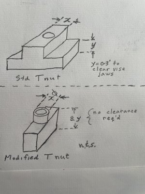
I have an idea that I think would allow you to use the T slot in the middle. Using a modified T nut: attach the nut to the clamping stud; insert in the slot; and rotate 90 degrees.
IMG_3345.jpeg
 
I had the same thought before too, but don't have any to try. I don't think they'd work without some modification, perhaps a jack screw in the tail for height adjustment, and they'd also be pretty tall. Roller rockers would better, or at least they "look" closer. I still think unless you had some sitting around for "free", you'd be better off starting from scratch with more suitable dimensions. I love repurposing stuff like that, and looking at stuff that's served it's original purpose and seeing what else it could be before sending it to the scrap pile.

Now that I look at a picture of one you’re right, kinda high. Maybe there’s something closer. I too like to draw on “parts bin Engineering” to repurpose things like that.

I saw a picture of an Audi OHC rocker with a central roller that was a better looking shape. The roller/shaft would have to be replaced with a hold down bolt.

File that idea under “keep an eye out” in case something interesting pops up.


Back on topic, I like some of your fixture plate details. I’ve been percolating an idea for a rotary table plate for doing multi angled thin plates, some of those details may show up when I eventually get there….

D :cool:
I think the roller rockers might be better because you could flip them upside down, and be closer to a workable geometry. The downside, is that even used they are more money than actual clamps lol. If you're scraping an engine, sure.....:D
 
I like your build and the design. Thanks for sharing and including the details. Well done!

I have had a similar fixture plate rattling around for a couple years - but mine only made it to the drafting board. It is now getting a little closer to the top of the list. Your post moved it up a couple spots in the queue.

My fixture plate could be used on the mill but primarily would be for welding/fabricating. On the mill it would be clamped to the table to hold a long part (a trade-off, move the vise vs gain rigidity). It would also have an attachment for one end that would hold a vertical component to make it work like a very large angle plate (brace for welding components at 90 degrees). The top surface would be 8.5" wide and about 24" long (bigger is better, but I don't want it to exceed 45 pounds.

Anyhow - my big take-away from your design is that your top surface components (slats) and the T slots are transverse (in the Y direction). My design (gathering dust on the board) was to have 2 longitudinal T slots (in the X direction). It had three longitudinal slats of 2.5" x 3/8" cold rolled and would be 8.5" wide (which includes two 1/2" T slots). So don't be surprised if your idea gets stollen and I build using transverse slats. 8-) Well back to the drafting table.

Your pictures also got me thinking about the T nuts. I had thought that I would need to have a spacer between the frame and the slats so that the T nuts could slide unobstructed. But my design had 24" long T slots vs your relatively short transverse T slots. I also noticed (in your design) that you have way more taped hole (for hold down bar clamp studs) than I had planned. I like that approach (thanks) since it improves versatility and makes the T slots less important. One minor issue with your design (as I understand it from your pictures) is that the T slots are not continuous and you cannot install a T nut in the centre portion, see marked-up screenshot pic:
View attachment 60219
I have an idea that I think would allow you to use the T slot in the middle. Using a modified T nut: attach the nut to the clamping stud; insert in the slot; and rotate 90 degrees.
View attachment 60220
Thanks Craig. I've seen tee nuts that have angled cuts on the end that allow you drop them into a blind slot and they will rotate and catch the groove when tightened. In the case of mine, I can slip one through the open end of the beam and place it in the middle, then run a stud/bolt down through it if needed. I will admit the slots weren't a big design factor for me, more of a bonus feature based solely on the fact that I only had 4" wide material to make up the top, and needed to space them out at "some" distance, or weld them up tight. Figured might as well make them 5/8" and allow some use for tee slots. I thought about premilling a slot through the beam to allow them to pass all the way through, but decided against it. May come to regret that someday, but it's easy enough to correct if needed. I thought the slot would decrease rigidity in the entire assembly, which was more of a priority than a tee slot that ran all the way through.

I always wanted a bigger fabrication plate too, but this one will no doubt see some welding action for small stuff at some point as a dual duty fixture plate. Especially for tig stuff.
 
Yep, I have two Oilite for that, ordered from McMaster Carr oh… 5+ years ago.

I should have another look at the drawings for that, it was mostly a lack of larger stock slowing me down.
If we're talking about the same bender, I'm sure I've got enough stuff kicking around for two. Next time you're out this way feel free to pop in and go shopping.

http://oxtool.blogspot.com/2012/08/rod-bender.html
 
Just got in from the maiden voyage. Worked exactly how I hoped. Now I didn't need to hold this part this way, there was enough meat to square up the edges, and grip in a vice, but that's not always the case, depending on shape and stock. Didn't notice any lack of rigidity issues either. Looking forward to getting a lot more use out of this. I also thought of a vice mounted angle plate while I was out there. Maybe that'll be the next side quest......

I modeled the plate so I can just bring it into my model and move it around to wherever I want to hold down holes. Draw the outline of the cutter paths/swath so I can make sure the bolts clear. Then I print it out 1:1 and lay it on the stock to punch my holes, and my 0,0 pickup at the center of stock.
bnsdRFg.jpeg


Drill press punched the holes out, then I took it to the fixture plate in the mill, layed some washers down, and matched up it's position as it is in the print and bolt it down. Taking care to square it up to the plate. Position on the plate doesn't matter, but squareness might, depending on the part. In this case it didn't matter at all as my parts were completely cut all around.
F8Dd9Nj.jpeg


Then I brought a pointed tool, in this case the same countersink I still had in the spindle from yesterday over to that center mark and zero'd out my g54. Close enough is good enough here.
ExOlAdw.jpeg


Touched my tools off on the top of the plate, and started cutting. First I spotted the holes (will gang parts and match drill/ream them), then I cut the profile with a 1/4" endmill. 15 minutes later, I had a finished part. Two actually. I did have to slow it down a bit due to chip evacuation, the stock coolant system isn't strong enough to blast the chips out of the slot, even though it sprays everywhere....so I kept having to blow it out periodically. Even still, I managed to square up the block for the other part of the pivot in the excello while it was running, jumping back and forth between machines using powerfeed :D. Almost felt like work lol. Shortly after I started cutting that slot I had to run down into the basement and grab this treadmill shroud I've been holding onto for YEARS for an extended coolant shield. Quick cut with a grinder and it worked perfectly. THIS is why I never throw anything out......:D I SO badly want to redo this entire enclosure.
wbEgPBE.jpeg

2O0MuL7.jpeg

10ksH3O.jpeg

eLjWlua.jpeg


Only a couple more "complicated" parts to whittle out and then I can start assembly of the grinder. Was kind of trying to do all the operations in batches and have all the parts done for everything before I started assembly. This is the first stuff I've programmed in about 8 months. Took a bit to get back into it, I'm definitely out of the groove but not gonna lie, I kinda of miss it. :(
 
Back
Top