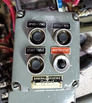
I have a 602 with factory power feed, the first generation with reeves drive. I reinstalled the factory wiring, and discovered that one of the wires in the power control box was loose. I am not sure where that wire goes. Per chance does anyone have schematic for the wiring in that box, or picture of the inside of that box?
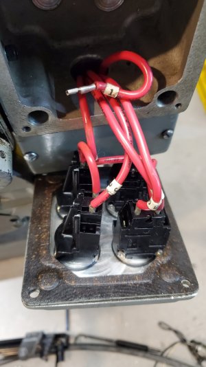
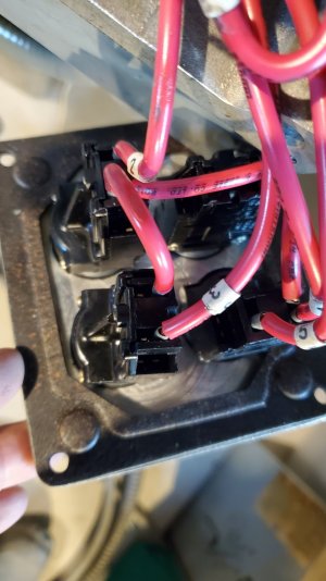
Wire labeled #1
Thanks. Dan
Looks like it goes to the master stop switch. But another photo of the wiring would help me confirm that. Try getting a photo from directly above the switches instead of on an angle like that.
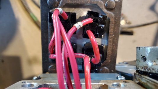
Assuming you can't find a wiring diagram, I'm pretty sure it goes here.
That's the only switch with only one connection. No such thing as a switch with only one connection.
That is based on assuming that the two wires there now are connected to the same connection with two blades.
Since it is a master stop, it is probably a momentary open or a momentary closed. You can use an ohm-meter or continuity Tester to find which one of the other connectors is either toggled on or off from the other circuit on that switch to find out which one serves one of those two functions.
If both connections exist on that switch, most likely that circuit activates a master contactor so you could use a jumper to momentarily activate a short or an open to determine which one of the two does what is needed.
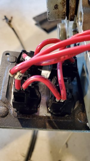
You are correct. The N.C. stop button receives 115v from stepdown transformer. (this is the disconnected wire (115v))
This 115v is daisy chained to the other 3 buttons.
The other buttons are configured N.O.
So this all makes sense now.. Standard configuration really