Tips/Techniques ELS discussion. Options. Experiences.

Tips/Techniques

Dabbler

ersatz engineer
I know of at least 3 C0636 (or equivalent) lathe owners in the group (now) only 2 in Calgary.

Janger and I were discussing several ideas and mods to the lathe, and I was wondering who all has this lathe?
One thing in particular, is how much torque does it take to do an ELS on one of these lathes. I am looking at ways to measure real-time cutting torque using the lead screw -- and checking several lathes out to get more than one data point.

I happen to be rewiring my lathe right now (the prev owner removed the electric break and changed the wiring considerably). So there's that as well.

If you feel sheepish about announcing it publicly, then PM me and we can talk...

-- it wouldn't hurt to have our own support group, of a kind...
 

Susquatch

Ultra Member
Administrator
Moderator
Premium Member
Hey Dabbler, I am not hugely familiar with what a C0636 is. When I search for it, I find Modern and King versions. Are they all the same? Or similar? Or varying all over the map? Also lots of different versions within the same manufacturer. Almost seems like "C0636" is a synonym for "nice lathe". You probably know all that, but I didn't.

I did a very quick search on C0636 on our forum and also found:

@ducdon


By flagging him here, he should get a notice and will be more likely to chime in on your thread.

Good luck on your subgroup.
 

Susquatch

Ultra Member
Administrator
Moderator
Premium Member
One thing in particular, is how much torque does it take to do an ELS on one of these lathes. I am looking at ways to measure real-time cutting torque using the lead screw -- and checking several lathes out to get more than one data point.

This is an interesting question for me and one I have wondered about too - quite independently of the lathe model. I've discussed it elsewhere but your thread bears very directly on my interests. I'm not interested in an ELS (yet anyway), but I am interested in understanding cutting forces better than I do.

I have lots of posts on the forum about this and none of the answers have been satisfying. It is my observation that most machinists think of cutting as a longitudinal force directed toward the lathe head. I don't believe that is a correct visualization at all.

Whatever forces are involved in moving the tip toward the head, they are minor compared to the downward forces applied to the top of the tool as the part rotates. That is why I like to think about the cutting edge of the tool being its top surface and in particular the top front edge - not the leading edge.

In my minds eye, I see the tool peeling a long chip off of the part like peeling an orange (still a valid image even with a chip breaker). Yes, a small force must be applied to keep advancing the tool. But again, in my minds eye this advancement can even be visualized as opportunistic as the left edge sneaks its way left under the peeling chip that is mainly being gouged out by the top of the tool.

If you have followed my previous discussions of this, I'm probably becoming quite tedious. I apologize for that. However, I believe your ELS discussion might be my very best opportunity to put this matter to rest once and for all in my own mind and perhaps for others too. If you are successful in making a measurement, the data will tell the story in a very compelling way.

Heck, this little adventure of yours might even provide data based substance to past discussions of hp and torque.

As I know you know, torque is what makes chips, and HP is how fast the chip pile grows. In the case of the leade screw, the torque required to advance the tool is not the strict stress of distorting the metal associated with the leade, it is the leade distortion divided by the circumference because the tool takes a whole revolution of the part to move by the leade distance - which is a much lesser amount.

How do you plan to measure the leade screw torque?
 
Last edited:
Actually if you want to do it get a the easiest way possible, get a digital torque wrench likely 1/4" as the readings will go low enough. Set it on peak trace, turn your machine on with the heaviest cut you are going to do. Engage your cutter manually. Crank you lead screw as fast as you can manually with the wrench and look at the peak torque double it as you will definitely push it faster than you can turn.

There is your spec.

You do the same things on mills.

When I did mine I came up with about 100in oz and doubled it, I contacted Teknic (Clearpath's manufacturer) they ask me what my set up was and potential wt of part, +/- 220in-oz.
 

Dabbler

ersatz engineer
Just to clue in the discussion into *general* terms, there are components of forces in several directions at once. I agree that the force exerted in 'Z' on the carriage advance toward the chuck is often overstated, but there has to be enough to maintain the the 'spiral' into the work.

The shearing force (downward) should be far stronger, and more important to resist, lest there be chatter.

The force I intending to measure (for the moment) is the torsion required on the lead screw to provide cutting forces at various depths in steel, using various cutters. Why??? because you cannot run an ELS without correctly specifying the size and power of stepper motor (or alternately servo motor)...

It would be best to measure this force on a larger sample size of the same lathe, so I can learn the variance in the same model as a baseline. Knowing your error band is essential to make good measurements and properly using those measurements.

I have in my evil little mind ideas to separate the two major forces in question at a later date, because as a result of our discussions (me and @Susquatch ) on the matter, now I need to know. That, unfortunately is far in the future and I have many (too many) irons in the fire.

How do you plan to measure the leade screw torque?

My current idea is to make a new end block for the C0636, that will permit an adapter for a standard Dewalt drill with a clutch. I intend on calibrating a specific drill and use it to power the leade screw. It seems sensible to use several specific and repeatable cutters, for several depths, in several materials (at a specific diameter). The academic would also test a bunch of diameters for completeness...

FWIW I am choosing a C0636, as it is popular, and the results might well inform the other models in the 14 X 40 category. For those with 13" or 12" lathes, it might be reasonable to assume that our results will translate, modified, to those lathes as well.
 

PeterT

Ultra Member
Premium Member
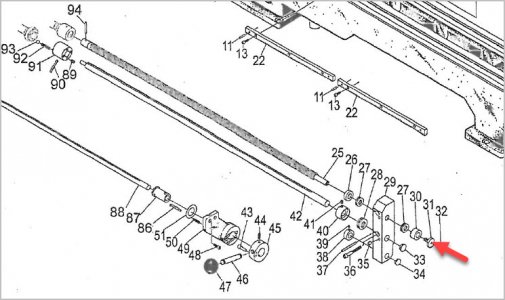
Excerpt from C0636A manual. I believe the Neanderthal over-torque prevention is via the shear pin within the coupler. You could substitute weaker materials against a common feed load so it fails earlier (and safer). But you would be limited by individual material strengths & I suspect dodgy data relating to meaningful numbers. If you could somehow adapt a maximum recording strain gauge in that area, might be more accurate & repeatable? Sorry, instrumentation is above my pay grade.

1671479907959.png
 

PeterT

Ultra Member
Premium Member
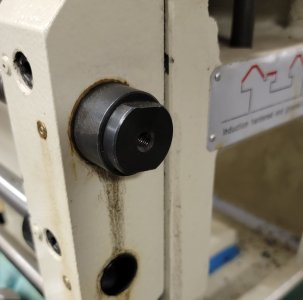
Not familiar with the lathe details but could you engage your drill/clutched/measuring adapter into what appears to be a threaded hole in shaft end?
(Not quite sure what the fastener does though & would only work in one rotation direction)
 

Attachments

  • EDT-2022-12-19 1.14.03 PM.jpg
    EDT-2022-12-19 1.14.03 PM.jpg
    77.7 KB · Views: 1

Dabbler

ersatz engineer
On a C0636, there is a plain rod at the end, approx 7/8 in diameter. there is a hole for a centre in the end o the rod.
 

Susquatch

Ultra Member
Administrator
Moderator
Premium Member
My current idea is to make a new end block for the C0636, that will permit an adapter for a standard Dewalt drill with a clutch. I intend on calibrating a specific drill and use it to power the leade screw. It seems sensible to use several specific and repeatable cutters, for several depths, in several materials (at a specific diameter). The academic would also test a bunch of diameters for completeness...

Good stuff @Dabbler.

It helps a great deal to know your purpose. I would tend to think your drill might be better adapted to the gear input side of the leade screw. You would need to remove the gear (or decouple it) anyway.

Fundamentally, @Degen s suggestion works, but he is alot younger than us and I would have no interest in trying to keep up with my lathe by hand that way.

@PeterT also has a viable idea. I don't think it would be that hard to make a set of shear pins of various designs (metal and cross section) and test till they don't break. Such an approach could even be calibrated by testing the shear pins with a torque wrench in a bench fixture.

Another approach would be to use a small motor and calibrate its torque output with electrical current flow. For a good motor this might be as simple as a calculation. But my guts say it's better to actually calibrate it. Thereafter you measure amps and calculate torque.

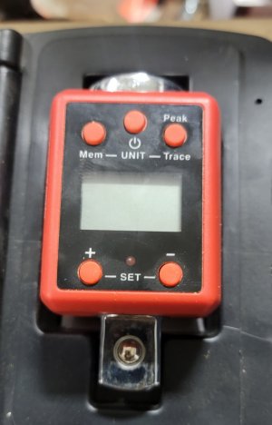
Another approach would build on @Degen s idea but use an electric motor instead of old man strength. I have a 1/2 drive torque meter that would do that job driving the leade screw with a 1/2 inch driver. I'll have to see if I can find a 3/8 or 1/4" drive torque meter like mine.

20221219_162804.jpg

Of course, if you really want to do a downtown job, you could make a custom torque meter for this job. I'd prolly still use a driver drill though, so why bother.

Of all of these ideas, I think building on @PeterT s shear pin idea is both easiest and most sure.

On a C0636, there is a plain rod at the end, approx 7/8 in diameter. there is a hole for a centre in the end o the rod.

Mine has a threaded hole in the end with drive flats.

20221219_132705.jpg
 
Good stuff @Dabbler.

It helps a great deal to know your purpose. I would tend to think your drill might be better adapted to the gear input side of the leade screw. You would need to remove the gear (or decouple it) anyway.

Fundamentally, @Degen s suggestion works, but he is alot younger than us and I would have no interest in trying to keep up with my lathe by hand that way.

@PeterT also has a viable idea. I don't think it would be that hard to make a set of shear pins of various designs (metal and cross section) and test till they don't break. Such an approach could even be calibrated by testing the shear pins with a torque wrench in a bench fixture.

Another approach would be to use a small motor and calibrate its torque output with electrical current flow. For a good motor this might be as simple as a calculation. But my guts say it's better to actually calibrate it. Thereafter you measure amps and calculate torque.

Another approach would build on @Degen s idea but use an electric motor instead of old man strength. I have a 1/2 drive torque meter that would do that job driving the leade screw with a 1/2 inch driver. I'll have to see if I can find a 3/8 or 1/4" drive torque meter like mine.

View attachment 29059

Of course, if you really want to do a downtown job, you could make a custom torque meter for this job. I'd prolly still use a driver drill though, so why bother.

Of all of these ideas, I think building on @PeterT s shear pin idea is both easiest and most sure.


Mine has a threaded hole in the end with drive flats.

View attachment 29061
Only takes a couple of turns to get peak. The meter you suggest is not sensitive enough, you are likely around 100 to 300 in-oz of torque.
 

Susquatch

Ultra Member
Administrator
Moderator
Premium Member
Only takes a couple of turns to get peak. The meter you suggest is not sensitive enough, you are likely around 100 to 300 in-oz of torque.

That's a couple more than this old man wants to try! LOL!

Anyway, I would have thought you need to at least take up the slack and get a good bite on the work to know what you really have. It's either that or peak is at start-up because of inertia. No experience to say that one way or the other - just a swag.

I believe the 3/8 digital torque adapters come in someplace around 10 ft lbs which is 120 in lbs. The 1/4 versions ought to be perfect. The main advantage is that it can be driven by a power driver instead of old man strength.

All that said, how sensitive do we need for this job? Don't we just need to know the max? And are we not going to apply a safety factor to that of at least 2 to satisfy @Dabbler 's needs?

I'll prolly build on that for more precise testing for my needs - which do not include an ELS (for now anyway).
 

Dabbler

ersatz engineer
Opinions vary, but socket wrench torque meters may/may not be applicable depending on who you ask.

I might give one a try and compare it to a calibrated torque limiter... Can't hurt!
 

TorontoBuilder

Ultra Member
I know of at least 3 C0636 (or equivalent) lathe owners in the group (now) only 2 in Calgary.

Janger and I were discussing several ideas and mods to the lathe, and I was wondering who all has this lathe?
One thing in particular, is how much torque does it take to do an ELS on one of these lathes. I am looking at ways to measure real-time cutting torque using the lead screw -- and checking several lathes out to get more than one data point.

I happen to be rewiring my lathe right now (the prev owner removed the electric break and changed the wiring considerably). So there's that as well.

If you feel sheepish about announcing it publicly, then PM me and we can talk...

-- it wouldn't hurt to have our own support group, of a kind...
Our new lathe is similar design... I'd be interested in our proposed methodology for measuring the torque requirements and participating. I'm going to convince my brother to upgrade this lathe to a smart lathe... not an ELS because I definitely want radius and taper turning in addition to threading.
 
Another even simpler alternative is call Tekic and ask them which servo to use. They are going to ask you some questions and they'll make a recommendation, and more likely them not an instant sale. You've been warned ;)
 

Susquatch

Ultra Member
Administrator
Moderator
Premium Member
Opinions vary, but socket wrench torque meters may/may not be applicable depending on who you ask.

I might give one a try and compare it to a calibrated torque limiter... Can't hurt!

There are obvious differences between limiters and meters/gauges, but they are mostly functional. Gotta ask why a torque meter might not be applicable (other than the difference between startup vs steady state). It's not immediately obvious to me.
 

RobinHood

Ultra Member
Premium Member
Perhaps formulae could be employed to calculate the feed force?

Here is an article that delves into the subject of lathe power required. They do calculate the feed force as well.


Here is an online calculator by submitool


whydontu

I Tried, It Broke
Premium Member
always willing to take one for the team. To settle this in my mind, tomorrow I intend to go buy a beam-style 1/4” torque wrench. I have lots of click ones, but only a 1/2” beam style. Set up a chunk of 303, a carbide insert cutter at 0.020” depth of cut, and measure the lead screw torque.
 

Susquatch

Ultra Member
Administrator
Moderator
Premium Member
always willing to take one for the team. To settle this in my mind, tomorrow I intend to go buy a beam-style 1/4” torque wrench. I have lots of click ones, but only a 1/2” beam style. Set up a chunk of 303, a carbide insert cutter at 0.020” depth of cut, and measure the lead screw torque.

You could also use a regular wrench and a fish weigh scale.

What feed rate, what diameter? I believe both will matter.
 
Top