Electric Motor Drive for compound

eotrfish

Super User
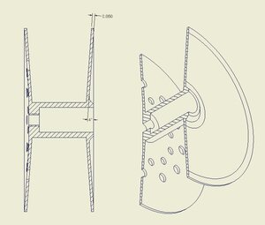
I make some fly reels which have a shallow (4Deg to 8Deg) taper on the flanges. I try for a mirror finish without having to polish after the parts come off the lathe. Turning the compound by hand without leaving any tooling marks is a PITA.

GENERIC SPOOL.jpg

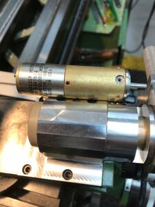
I found a couple of small 27V DC gear motors in my collection of "useful someday stuff" - always good to have backup:)

IMG_1993.jpg

IMG_1992.jpg IMG_1988.jpg

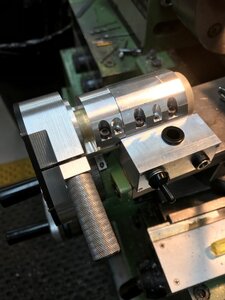
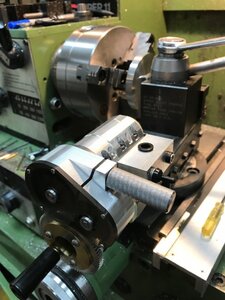
The whole assembly is secured to the top of the compound with 4 8-32 socket head caps.

Since the motor is DC it can be reversed. Although the motor is rated at 27VDC I've run it from 12VDC to 40VDC. All the voltage change does is change the compound feed rate. So far 27VDC seems just right for a near mirror finish.

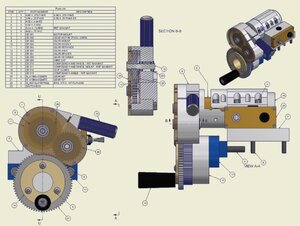
The idler gear train pivots on the motor centerline to engage or disengage the gear mounted on the compound handwheel - effectively turning the compound feed on or off.

COMPOUND TAPER.jpg
 

eotrfish

Super User
I gave it a try but found Google/You Tube to be a pain. PM me with an email and I'll send you an MP4 file.
 
Last edited:

Bofobo

M,Mizera(BOFOBO)
Having power feed is pretty awesome, I recently found a hack for using a T shaped bar in a drill but my newer machine has face feed but I’ll keep the idea in case I get another mini machine. I can see many older lathes benefitting from this machine. Hardest part of having the “one day box of bits” is justifying its space but one of these projects a year is totally worth it IMHO. Great work!
 

Janger

(John)
Administrator
Vendor
@eotrfish - is making Fly Reels a bit of a business for you? A labour of love I"m sure. Nice. Very Nice. How did you approach making the gears?
 

eotrfish

Super User
Janger

I have sold a few but the market for bench made reels is quite small. I fish many of them and/or just give them away. Some sit in my display cabinet.

To be clear - I did not make the gears. I purchased them from SDP-SI - https://sdp-si.com/. I then bore/face them as needed to fit the desired assembly.

The gear train design was a bit tricky because I didn't have a variable voltage power supply on hand. This meant that I would be stuck with a feed rate dependant on the gear ratio selected.

So these are the design steps...
- determine compound feed rate to produce near mirror finish at appropriate lathe R.P.M. - I'm turning these at 200 r.p.m.
- measure gearmotor output speed at rated input voltage 27 VDC (and a few voltages above and below rated voltage)
- pick a gear ratio that fits these criteria
- pick a gear size that will fit on the compound hand wheel
- pick a gear size of the correct ratio to fit the gearmotor
- design the housing to provide clearance between the drive gear and driven gear
- design the idler - I originally considered using change gears on the output side of the idler but found I didn't need to.

This was really just an excercise is packaging the correct components.

I don't recall the exact compound feed rate but I think that I ended up with somewhere between 0.0015" and 0.002" compound feed per revolution, which gives me the desired finish. I can use a 40VDC supply and turn at 300RPM to save a little time roughing the taper.
 

kylemp

Well-Known Member
Having power feed is pretty awesome, I recently found a hack for using a T shaped bar in a drill but my newer machine has face feed
Unless I'm not seeing it right, this is compound feed which pretty much no machines have as far as I'm aware.. It'd make cutting angles using the compound a lot more consistent which is what I'd want to use it for. I've considered making an air attachment to do this before but this makes a lot more sense.
 

eotrfish

Super User
kylemp

You're seeing this right - it is a compound feed and I could not find any lathes with this feature. Of course my buddy who owns a machine shop just chuckled and said "that's what CNC is for".

I just did a web search and found one guy who adapted a generic mill power feed - might work for you.
 
Top