Drill fixture for lathe

Janger

(John)
Administrator
Vendor
Well we seem to have lost some content due to the server crash. The ones I’ve noticed we had a ELS thread, a C0636 & other 14x40 lathe thread and this thread to get going again.

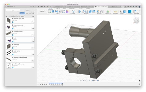
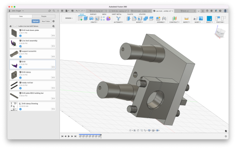
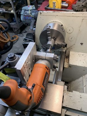
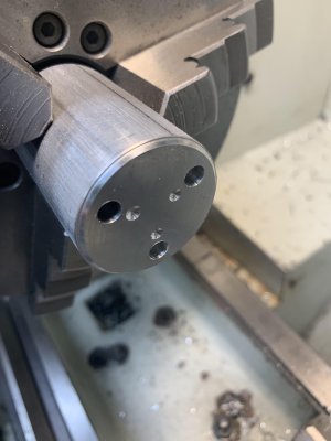
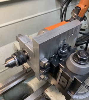
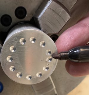
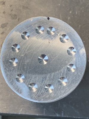
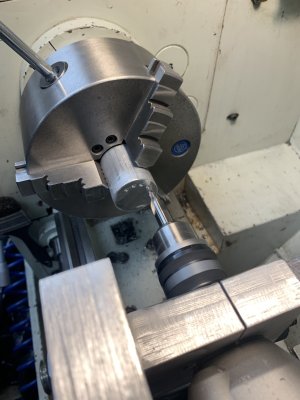
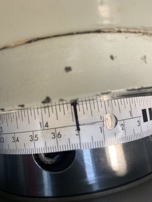
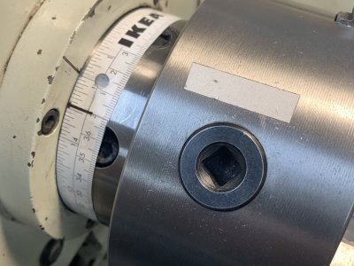
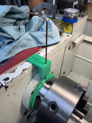
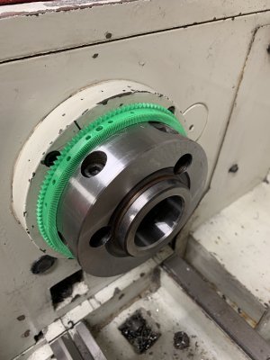
I’m working a drill fixture for lathes to allow holes offset from the Center axis. Pics….
 

Attachments

  • 394BC0DB-236E-4407-8570-C79169DDD4C1.png
    394BC0DB-236E-4407-8570-C79169DDD4C1.png
    929.7 KB · Views: 4
  • 4BC62480-F081-4AF6-B02E-D23EC2BAE8E1.png
    4BC62480-F081-4AF6-B02E-D23EC2BAE8E1.png
    890.3 KB · Views: 4

Janger

(John)
Administrator
Vendor
A picture of the result. It is working. The drill is held pretty solid by just the front clamp so I don't even need the supports on the drill body. One disappointment is the drill bearings have some slop so the chuck wiggles reducing accuracy - perhaps by +/- 0.010" or 0.020". It is just a hand drill. I've successfully drilled a 3 hole pattern for a flange as a test. This will be useful for the occasional hole required off center. Especially when the part is long and won't fit in the mill (like a lead screw). I'll try to post more pictures when the forum supports large image files again.
 

Attachments

  • IMG_3050.jpg
    IMG_3050.jpg
    426.7 KB · Views: 15
  • IMG_3055.jpg
    IMG_3055.jpg
    263.5 KB · Views: 15

Janger

(John)
Administrator
Vendor
Now I'm going to try to drill a starting hole every 15 degrees with my silly Ikea tape measure angle guide.
 

Attachments

  • E1720B9E-97FF-4EEC-8249-FB66BEE58B1B.jpeg
    E1720B9E-97FF-4EEC-8249-FB66BEE58B1B.jpeg
    406.1 KB · Views: 6
Last edited:

Janger

(John)
Administrator
Vendor
Hmm results. I had to go with 30 degrees too tight for 15. Where I’m pointing is off a bit. Checking the numbers I think the circumference is actually 378.1mm not 379.1mm. So the last hole should have been at 362.3mm instead of 363.3mm. One or two other holes look a bit wonky. I probably missed aligning the spindle to the tape…
 

Attachments

  • 5CA07A97-1259-47CF-AB6E-FD9CDF09A651.jpeg
    5CA07A97-1259-47CF-AB6E-FD9CDF09A651.jpeg
    328.8 KB · Views: 5

Janger

(John)
Administrator
Vendor
Well the mitutoyo big caliper says the spindle is 117.3mm in diameter which is 368.5mm in circumference. Ikea thinks it is 378.1mm. That's a lot almost 1cm. I No no no. Wrong reading it wrong. Ikea says 368.2. I'm asking a lot of a free plastic tape measure! :> That's actually pretty close!

I am going to have to regroup. This needs more thought.

I could mount the rotary table to the chuck and position the spindle at specific degrees on the clock and mark the spindle perhaps. How do people do this?
 
Last edited:

Janger

(John)
Administrator
Vendor
Now that I'm reading right... doh! ... I'll try this again. I drilled the last hole at 345 degrees at 363.3mm in circumference - it should be 352.9. which probably explains the wonky drill pattern.
 

YYCHM

(Craig)
Premium Member
Well the mitutoyo big caliper says the spindle is 117.3mm in diameter which is 368.5mm in circumference. Ikea thinks it is 378.1mm. That's a lot almost 1cm. I No no no. Wrong reading it wrong. Ikea says 368.2. I'm asking a lot of a free plastic tape measure! :> That's actually pretty close!

I am going to have to regroup. This needs more thought.

I could mount the rotary table to the chuck and position the spindle at specific degrees on the clock and mark the spindle perhaps. How do people do this?

You lost me..... What are you trying to do?
 

Janger

(John)
Administrator
Vendor
Ah! Right Craig I’m not being too clear. I’m trying to rotate the lathe spindle in 30 degree increments to make a bolt round pattern on a round part. Like this.
 

Attachments

  • 6C4952F7-9D76-4C22-AF28-B9F7F090FDCA.jpeg
    6C4952F7-9D76-4C22-AF28-B9F7F090FDCA.jpeg
    372.6 KB · Views: 2

YYCHM

(Craig)
Premium Member
Ah! Right Craig I’m not being too clear. I’m trying to rotate the lathe spindle in 30 degree increments to make a bolt round pattern on a round part. Like this.

This is an indexer I made for my mini-lathe...

3.JPG

That's a 120 tooth gear from PMS Hobbies, so 3 deg increments.
 
Last edited:

PaulL

Technologist at Large
Premium Member
Ah! Right Craig I’m not being too clear. I’m trying to rotate the lathe spindle in 30 degree increments to make a bolt round pattern on a round part. Like this.
My little indexing jig has an unfortunate amount of backlash that I have to take out pretty carefully every time I move the index (yes, I need to remake my spindle now that I'm a bit better at this machining thing).

Could it be something as simple?
 

Janger

(John)
Administrator
Vendor
I'm going to follow Craig and 3D print a plastic indexer. maybe with 15 degree index holes. 3 degree notches. 1 degree marks?
 

DPittman

Ultra Member
Premium Member
On my little lathe I made a disc with a printed degree (or numered) label that attaches into the back of spindle hole with a expanding tapered plug. I then just use a simple pointing needle in a magnetic stand to indicate my position. The bigger wheel/disc you have the more potential accuracy it can have. My disc is an old vinyl LP (Blue Oyster Cult Club... cuz that matters). The only thing I haven't been able to incorporate yet is a locking mechanism to hold the spindle from moving. However if I am carefull it seems to work surprisingly well without. I've cut a few small gears on my lathe with it and indexed a few items.
 

Janger

(John)
Administrator
Vendor
More pics
Yay Josh fixed the picture upload!
 

Attachments

  • 292D647B-EDDC-4746-9FDA-BE7A2B8B3612.jpeg
    292D647B-EDDC-4746-9FDA-BE7A2B8B3612.jpeg
    447.9 KB · Views: 13
  • EE2DFDA2-A8B6-4BB1-99EE-91FCBB5E5AD4.jpeg
    EE2DFDA2-A8B6-4BB1-99EE-91FCBB5E5AD4.jpeg
    295.3 KB · Views: 13
  • B50C2B00-D343-4859-853F-11F88E153A62.jpeg
    B50C2B00-D343-4859-853F-11F88E153A62.jpeg
    222 KB · Views: 12
  • 48C167A5-455E-47A1-BAE9-69E3ABA27FC5.jpeg
    48C167A5-455E-47A1-BAE9-69E3ABA27FC5.jpeg
    406.1 KB · Views: 13

Susquatch

Ultra Member
Administrator
Moderator
Premium Member
Actually the plastic ring part works pretty good. The piece to hold the indexing pin is way too flimsy - needs to be metal or printed thicker and denser. I think a threaded pin would work well.

Why is the pin even needed? Isn't your indexing mark sufficient?
 

Susquatch

Ultra Member
Administrator
Moderator
Premium Member
Actually the plastic ring part works pretty good. The piece to hold the indexing pin is way too flimsy - needs to be metal or printed thicker and denser. I think a threaded pin would work well.

Further to that, you could even make a sort of vernier scale at the indexing mark and use that to align the spindle.

I doubt the pin could ever stop the spindle from turning. Just put the lathe in your lowest gear, turn and index the spindle using the motor belt, and put a stop cog in the lead screw gears. Just don't forget to remove it.
 
Top