• Scam Alert. Members are reminded to NOT send money to buy anything. Don't buy things remote and have it shipped - go get it yourself, pay in person, and take your equipment with you. Scammers have burned people on this forum. Urgency, secrecy, excuses, selling for friend, newish members, FUD, are RED FLAGS. A video conference call is not adequate assurance. Face to face interactions are required. Please report suspicions to the forum admins. Stay Safe - anyone can get scammed.

Double reduction worm and wheel

thriller007

Well-Known Member
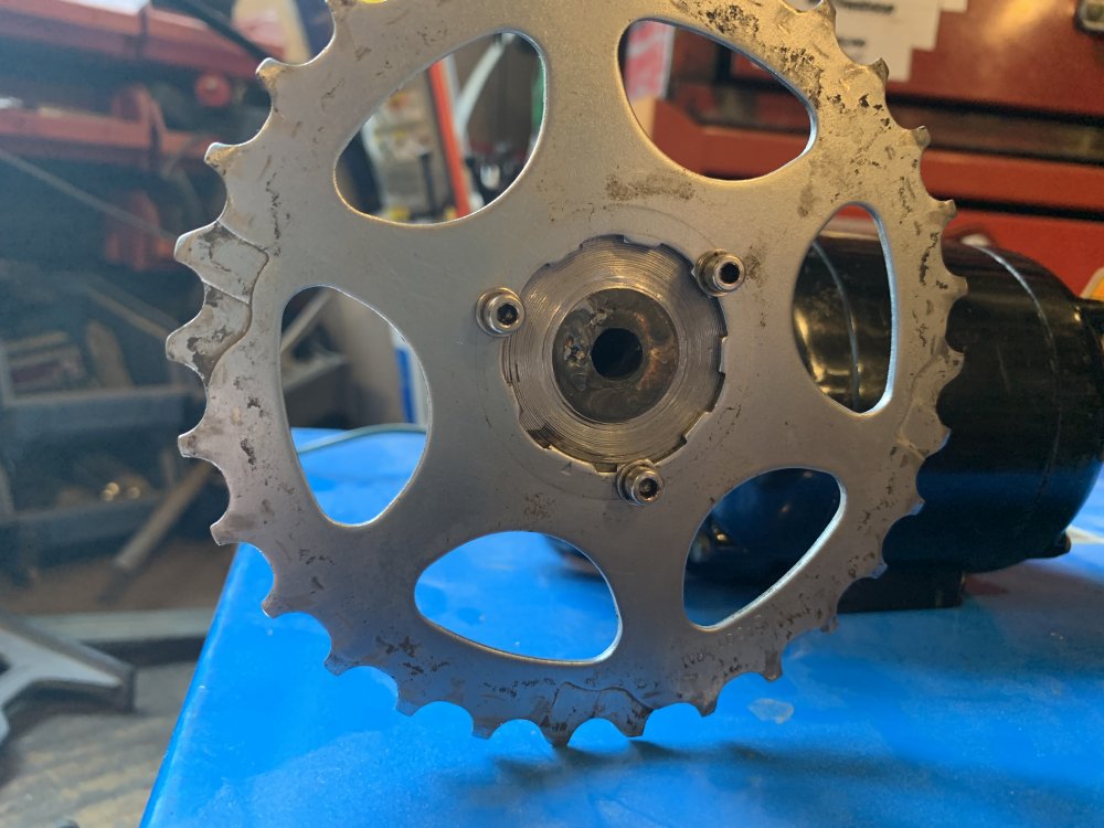
The ideas were going through my head as to how to make a power feed for lifting and lowering the head on my small mill. It’s an awkward area to use the current hand wheel in tight quarters. A friend had an old (1965 ish) small 110v motor with a double Reduction worm and wheel that had a no load output of about 22 RPM. Now the wheels are turning 22 RPM is kind of slow so what can I use to speed this up and connect to my hand wheel? Why not use chain and sprocket’s from an old mountain bike. Build some adaptors for both the hand wheel side and the output shaft of the motor. Build a plate that mounts on top for the motor to mount to and experiment from there. Make the sprockets bolt on so you can play with some different gearing. And then....to be continued...
 

Attachments

  • 3E95CA7B-7640-492D-A1E5-A33D335C3FA5.jpeg
    3E95CA7B-7640-492D-A1E5-A33D335C3FA5.jpeg
    117 KB · Views: 0
  • F1ADE897-D9D8-4684-B6BA-52E6CD8FEBBA.jpeg
    F1ADE897-D9D8-4684-B6BA-52E6CD8FEBBA.jpeg
    110.8 KB · Views: 0
  • 3C0B0524-9155-4A34-BADA-2E6B40674717.jpeg
    3C0B0524-9155-4A34-BADA-2E6B40674717.jpeg
    122 KB · Views: 0
  • CF15402D-94CA-446F-9135-B4E2864C1020.jpeg
    CF15402D-94CA-446F-9135-B4E2864C1020.jpeg
    92.5 KB · Views: 0

thriller007

Well-Known Member
Well I have had some success With the preliminary testing and the gearing I currently have it lowers at about 50 to 55 rpm. It goes up a bit slower at about 40 to 45 rpm. Time to put an amp meter on it to see what it is drawing for current and think about some gearing changes to speed it up slightly.
 

Attachments

  • 24A8F6A2-8B4B-4710-B8EE-9390FCEA2F5D.jpeg
    24A8F6A2-8B4B-4710-B8EE-9390FCEA2F5D.jpeg
    86.3 KB · Views: 1
  • 0A915DA6-D9F2-4639-A14B-6F84255534ED.jpeg
    0A915DA6-D9F2-4639-A14B-6F84255534ED.jpeg
    88 KB · Views: 1
  • 5A87522F-BB19-4397-8E24-4C1BAA4E872E.jpeg
    5A87522F-BB19-4397-8E24-4C1BAA4E872E.jpeg
    133.3 KB · Views: 1
  • 53778DF1-CF32-4DBD-BAA5-2F4209115148.jpeg
    53778DF1-CF32-4DBD-BAA5-2F4209115148.jpeg
    90 KB · Views: 1

Tom O

Ultra Member
When I use it I just crank by hand you have to undo/redo the gib lock anyways. I would seriously consider a cooling fan on top of the motor though it really helps temp wise there is not enough cooling fins 4 I think, I should still have the file if you want I could print you up one.
 

thriller007

Well-Known Member
When I use it I just crank by hand you have to undo/redo the gib lock anyways. I would seriously consider a cooling fan on top of the motor though it really helps temp wise there is not enough cooling fins 4 I think, I should still have the file if you want I could print you up one.
Thanks so much for the information. I would love to take a look at what yours looks like. I take it you’re talking about 3-D printing and I have no capability for that. Also do you use anything else for the counterweight or spring on yours?
 

thriller007

Well-Known Member
Ok well that project seems to be working. It’s not quite as fast as I wanted but totally usable. Added a up down switch and mounted a capacitor. Time to move on to the next project. The powered x-axis power feed modification......
 

Attachments

  • EFE2FE7A-555B-4BF1-95BA-A38FC6B9DDA1.jpeg
    EFE2FE7A-555B-4BF1-95BA-A38FC6B9DDA1.jpeg
    89.8 KB · Views: 0
Top