Deckel FP3 L : Input Shaft & Pulley Repair

RobinHood

Ultra Member
Premium Member
We’ve all been there: work on something seemingly unrelated and then realize that, wait a minute, woulden’t it be great to use this machine for that task.

Well, I am designing and figuring out a way to make a gap piece for my CMT Ursus 250 that is missing. I am making it up in wood right now. I’ll post the thoughts, design ideas and manufacture of it on the CMT Ursus lathe series thread.

So I thought why not use the FP3 mill to make the gap piece? Good idea, except it has this ”funny” noise when it runs. So I started digging into it a bit, and promptly opened a big can of worms…

The input shaft pulley is worn very badly. The key is chowdered up. The 25mm shaft has a worn spot. The manual hand wheel to rotate the input shaft for ease of gear changes is missing and with it the retaining plate to hold the pulley onto the shaft.

8743EF16-EB0B-4622-97DA-2EFE0872F355.jpeg
EB882180-8C1E-49BD-B30B-0FA9ED6E0EC1.jpeg

I’ll take a picture of the shaft once I get it out of the machine…

Which brings me to the next problem: there is a thrust washer that was induction welded onto the input shaft at assembly. It is used to provide a means to set the bearing pre-load of the nested, larger, secondary shaft which is coaxial with the long input shaft which runs through it. The thrust bearing is item 2001 452 in the diagram below.

Here is the parts diagram showing the assembly.
6E9987F3-516A-491F-9BEA-3B15807AC99E.jpeg


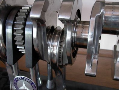
There are three supports for the two shafts: one on each end of the gearbox and one on the central bulkhead. The input shaft is the lower of the two shafts in this picture. It runs all the way through the bigger shaft on the right with the bull gear and the other 4 gears to its right.
6921E713-9FDA-4D43-A30E-CA7D32CE9020.jpeg

And here is the welded thrust washer
475B4FDB-7535-4F33-9B3D-E53881441725.jpeg

The way this needs to come apart is for the long input shaft to slide out the left side as viewed from the access panel. The cluster gear (2001 30 416) will slide on the splines and remain inside the gearbox as the shaft moves left. However, the welded washer (2001 558) will not allow the gear set to slide off the right side. Anything to the right of that washer (2001 31 414) is part of the nested secondary shaft and would remain inside the gearbox as the smaller input shaft is pulled out through its bore.

So, I need to (most likely) destroy the welded washer, grind the splines sufficiently to allow the cluster gear to slide off, and pull the shaft out. I will get all the dimensions I can off the washer before destruction. I’ll need to make a new one for re-assembly. Not sure why it was so important to weld it to the shaft in the first place as it sits hard against the shoulder created by the splines to its left. Perhaps there is an anti rotation requirement? I won’t have a way to weld it in place. I may look into making some sort of key for it.

Before I start destroying the washer, I’ll revisit the whole thing again to make sure I have not missed another solution.

Have any of you come across a similar situation? What did you do? I am wide open to suggestions on this one.
 

Dabbler

ersatz engineer
Without being aboe to see it, it seems odd to have welding inside the gearbox... Is it possible this is not factory?
 

RobinHood

Ultra Member
Premium Member
Agreed, why weld?

Just based on the uniformity of the heat discolouration all the way around the shaft and the washer, it was done by someone with a lot of skill and / or special equipment for the task - ie not a hack/afterthought. I checked again, not a braze job nor TIG welding tacks. Pretty sure is was induction welded - who has that kind of equipment?

Sure, come on over and take a look; the more eyes on the situation, the better…
 

Dabbler

ersatz engineer
We went by yesterday on errands, but too busy/too late to drop by. perhaps in a day or 2...
 

Darren

Ultra Member
Premium Member
Hard to believe that was welded in place, and for what reason? There has to be another way. Do you really need to take it apart? Perhaps the shaft can be repaired in place?
 
I suspect that the intermediate bearing in the casting just right of the welded washer is removed to get the gears and shaft out. It also looks like it might be a 2 part shaft in the 2001-464 area.

I likely doubt that they would weld in place as it would be to costly from an alignment stand point, more likely outside the machine and assembled. Trick is finding how they did it to do the reverse.
 

Brent H

Ultra Member
Hey Rudy,

Do you have the part descriptions with the drawing? I am wondering if you removed all the end parts If 2001-30 416 will slide off as one assembly and is being retained by bearing 6005 DIN 625. The “welded washer” might come off then or is part of that assembly as it looks like it stops the gear movement.
 

RobinHood

Ultra Member
Premium Member
First of all thanks for everyone’s input, much appreciated as it gets me thinking in different ways.

The set-up is surprisingly complicated and clever at the same time. The parts diagram only has the identifying numbers, no description. I’ll only use the “- xxx” nomenclature going forward.

Please refer to the marked-up diagram below.

4378FEA6-582C-434F-8777-C60EEFF30F66.jpeg

Here is what I have been able to determine today. The hollow, outer, 35mm shaft is supported by a 6007 bearing on the left which sits in a through bore in the center gearbox rib. The right side of the shaft has a plain bronze bearing pressed in and is supported by the solid shaft running through it; I‘ll call input shaft. The length of this shaft is the distance between the welded washer (-558) and the bronze thrust washer (-452). The left most gear (smallest of the 5 on that shaft) is integral to the shaft. The 4 larger ones to its right seem to be keyed to the shaft and retained with a large C-clip located just behind the right most gear. Immediately to right of the bronze thrust washer (-452) is bearing 6305 which sits in a housing (-464) which in turn is located in the gearbox wall and retained by 3 screws. Bearing 6305‘s inner race supports the input shaft - and in turn also the second, hollow shaft with its plain bearing that sits on the input shaft. The endplay of the second hollow shaft is taken up between the welded washer (-558) and the outside portion of the inner race of bearing 6305 through the bronze thrust washer (-452) and the power feed drive sprocket’s boss (-367) [which also has a lip seal installed around it] and the pulley nose extension and the pulley retaining bolt. Basically the yellow arrows show how this hollow shaft is prevented from side to side movement by constraining it with the input shaft that runs through it.

None of the components can be removed from the second (hollow) shaft as long as any part of the through shaft is in it. The input (through) shaft will not go through to the right as the welded washer (-558) (and the splines to its left) have a larger diameter than the bore of the hollow shaft.

So the long through shaft has to move to the left. The cluster gear set (-30 416) sitting on the splines have a larger diameter than the bore in the GB case. So they need to stay inside the gearbox for disassembly while the shaft is pulled through them. The welded washer (-558) stops the cluster gear from sliding off the spline on that side.

One thing that I have not yet tried is to remove the housing (-464) of the 6305 bearing and sliding the complete inner and outer shaft assembly together all the way to the right until the gear touches the GB wall. Then, on the left side, remove the 6005 bearing from the shaft and its housing (-273). Hopefully there might be enough room to slide the cluster gear set (-30 416) off the spline to the left. If that would work, then the through shaft could be pulled out through the left GB bore as the splines / welded washer are smaller in diameter than the hole in the wall.

I have taken rough measurements to see if there would be enough room gained by the above procedure, but I think the cluster gear set is wider than the space gained. It might be worth me trying it anyway just to make sure that this does not work. Sometimes there are ways to just angle things a bit to get that extra thou of clearance to make it work…

I have two sets of knowledgeable eyes coming out tomorrow for a brainstorming session to help me solve this problem.

Stay tuned…
 

PeterT

Ultra Member
Premium Member
Seems odd that they wouldn't show an important aspect like how the shaft assembly is removed. Undocumented magic trick! Is there a document / parts catalog by which you can examine the parts in isolation as opposed to that GA isometric drawing? Do you think there is a chance that the shaft segments join within a bearing or collar which keeps it aligned? I've seen opposing halves joined this way. Can't find a picture but I can sketch it if you like. Or maybe its cousin, the Hirth coupling.
 

Attachments

  • SNAG-2022-03-15 9.32.16 PM.jpg
    SNAG-2022-03-15 9.32.16 PM.jpg
    177.9 KB · Views: 12

RobinHood

Ultra Member
Premium Member
As far as documentation, this is all I have. No “exploded view”. No “how to“ instructions as far as disassembly of the GB.

I did mention to @Dabbler , that this mill has “field disassembly” items and “factory only” items - the horizontal spindle cartridge being one of them. They allow enough disassembly to clean and repack the bearings. But there are components on the spindle which can only be serviced in the factory.
I have not found anything wrt this gearbox. Maintenance for it consist of charging the oil at certain intervals, checking belt tension and that’s about it. I am sure the machine was not designed to have a pulley come lose and get wallerd out by the harder shaft. But it happened and I intend of repairing it. For best results the shaft needs to come out so I can grind it between centers and make a corresponding pulley bushing for it with the key way.

The CMT Ursus 250 lathe uses shafts coupled within a mounted assembly in the QCGB as there is no other way to fit all the components coaxially otherwise (because of bearing diameters, gear sizes and support bore dimensions). So yes, that thought has crossed my mind. I am pretty sure that the input shaft is one approximately 2 ft long solid piece and the other hollow shaft is about 1 foot solid.

This gearbox has 18 speeds, done on two shafts, each with secondary, independent rolling elements on them. The power path is from the pulley, through the hollow shaft to the left side of the GB. Gear ratios are then selectable and transmit the power to an upper shaft. It transmits the power all the way to the right side of the GB, where more ratios are available. Then the power flows back down onto the lower, outer, (hollow) shaft and is transmitted via bull gear (and HI / LO range) up to both the horizontal and vertical spindle. Gear selection is achieved vial a cam plate with 4 shift lever arms. The cam plate is controlled by only two knobs from outside the GB. Quite ingenious and very compact. And super smooth shifts.

I am sure I’ll eventually find a way to get it apart. After all, they put it together somehow. I am probably missing something obvious or some “hidden” trick.

Speaking of hidden tricks: to get the operator side cover off, one needs to go to the opposite side, remove an access panel and deep within it there is a M8 x 45 SHCS that releases the center support of the cover - who would have dreamed of that? Deckel did… The other, top fastener of said cover is hidden/integrated into the Stop/Start switch mounting bracket! Again very clever.
 

RobinHood

Ultra Member
Premium Member
Here is an overview of the mechanical power distribution on this mill. Two spindles, power feed on all three axis with mechanical rapids. The shafts (not shown in this diagram) I am struggling with is indicated by the red arrow. You can see how all the gears are nested and their relative size so there is no sliding anything out the side; the shafts need to come out in order for the gears to come out.

6DD69241-3B5E-4661-9175-38FDEF5E2815.jpeg
 

Darren

Ultra Member
Premium Member
Just a thought, but can you make a new hub for the pulley that would bridge the damaged area of the input shaft, so you can avoid disassembly?
 

Brent H

Ultra Member
@RobinHood : from your drawing above it appears that the welded washer is part of the gear assembly and not the shaft?? Could it be that the shaft can be drawn out and is a separate entity? Maybe? Splined or ? to the second gear cluster? I know that tapered pins can virtually disappear when filed to the shaft.
 

kevin.decelles

Jack of all trades -- Master of none
Premium Member
from your drawing above it appears that the welded washer is part of the gear assembly and not the shaft?? Could it be that the shaft can be drawn out and is a separate entity? Maybe? Splined or ? to the second gear cluster? I know that tapered pins can virtually disappear when filed to the shaft.
@RobinHood Agree - don't rule out the shaft on a shaft on a shaft possibility. Looking forward to the solution -- like you said, they got it in there somehow.
 

PeterT

Ultra Member
Premium Member
I wonder if the heated area is equivalent to heat shrink fit tool holdesr? ie. relatively low expansion, but providing the grip/retention. The tool holder has similar heat discoloration. I know nothing about these other than seeing them in catalogs & such. May not help you if you don't have a means to bring in instant, focused heat.


RobinHood

Ultra Member
Premium Member
Just a thought, but can you make a new hub for the pulley that would bridge the damaged area of the input shaft, so you can avoid disassembly?
YES! That is going to be the solution.

I’ll do a more detailed write up later tonight explaining what we found and what modifications will be required to one existing part and then the new pulley hub…
 

RobinHood

Ultra Member
Premium Member
The two John’s stopped by today.

It was determined that the steel washer was indeed induction brazed (not welded as I thought) onto the input shaft at the end of the spline inside the GB after assembly. The only way to get it out would be to apply heat to melt the braze and release the washer from the shaft.

Took a close-up of the brazed washer. You can just make out the yellow brazing material at the interface of the washer to the shaft.
C5E6443C-F1BD-44DE-A582-F4CFF1291AE0.jpg

Here are three pictures of the input shaft. First one shows both the power feed sprocket and the pulley. The second shows the shaft with the pulley removed and the worn area close to the sprocket. The last one has both components removed and the wear is clearly visible.
D3AF0F1B-5FCE-42F3-874B-DC0072024634.jpeg
E8B0A3A3-7028-46BD-93E2-4C4CE13FC932.jpeg
3E60F89B-CA3A-4A51-888D-1EC265FCD141.jpeg

So the solution will be to shorten the sprocket body, remove the worn out pulley center including the extension. Then I will make a new, longer bushing to insert into the sheave. One side will be as along as the original “snout” and the other side will be long enough to bridge the worn area of the shaft and still leave enough length on the shortened sprocket body to fully engage its key. I won’t have to remove the shaft from the GB.

A rough sketch of the solution.
AB7DF213-58E1-407C-8D31-698ADE2E2473.jpeg

As long as the overall Z dimension remains the same, I will be able to still preload the thrust bearing of the second shaft inside the GB. Also, if Y remains as original, there will be no belt tracking issues.

I have a suitable piece of 12L14 to make the new hub out of. I’ll probably just use red locktite and light press fit to mate the CI pulley to the new hub. Another option is to make a key way and a key if there is enough wall thickness on the new hub.

One challenge will be the long key way inside the hub bore. It is only 25 mm in diameter but will be more than 100 mm long. I don’t have a 6 mm broach - might have to buy one and make a corresponding broach bushing. I might be able to make a broaching tool for use in the BP milling machine and use it - although 4” long and only 1” of height might not be stiff enough and cause all kinds of problems. I do have a good 1/4” broach. I could make a stepped key: 1/4 to 6 mm. Time will tell I guess…
 

Darren

Ultra Member
Premium Member
For the 4" long keyway, could you make a built up assembly? A 25mm id sleeve, say 32mm od, 4" in length. Cut the keyway with an endmill along the 4" length. Make a 32mm id outer sleeve. Say 38mm OD. Slip the outer sleeve over the inner, check and adjust fit, Tig weld at the ends while on a mock up shaft., maybe a few plug welds too. Might be easy enough to do.
 

RobinHood

Ultra Member
Premium Member
That could be an option. Thanks for the idea.

I think there may be a problem with my plan to shorten the boss on the sprocket: they TIG welded the outboard side of the key way shut (after broaching it all the way through). This allows for a hard stop on its key. The pulley’s inboard face sees a hard shoulder and thus can be retained on the shaft with some pressure without transferring an overly large pressure onto the internal thrust bearing and thus preloading it too much.

Upon closer inspection, it seems that the sprocket presets the thrust endplay with the carefully placed weld (not the pulley retaining bolt). It also explains why there are two individual keys in the shaft and not one continuous one - need to think about what I could do to solve that problem…
 

Darren

Ultra Member
Premium Member
What if you machined a short length of the OD of the sprocket hub, next to the worn area, and then counter-bored the end of the new repair hub to slip over it. Then you would not have to alter the sprocket hub length.
 
Last edited:
Top