Cutting Threads

terry_g

Ultra Member
I picked up a couple insert type threading bars a left and a right. They are decent quality for the price.
Rather than thread toward a shoulder I usually thread with the lathe in reverse and the tool bit upside down.
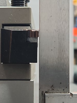
With the treading bar I was able to cut threads with the cutter on the back side of the stock right side up.
I like to watch the chips coming off as the threads cut.
This was practice cutting 5/8" 18 threads on a piece of mystery metal. I fed the bit in straight next time I will
try cutting with the compound set to 29 degrees.

IMG_3281.JPG
 

Susquatch

Ultra Member
Administrator
Moderator
Premium Member
Looks like a great setup. I love threading and do a lot of it. The main thing you need to watch when you thread using unconventional approaches on the back or inside is the tool helix angle. Rather than explain here, (Lotta words) I'll come back and edit this post to add a nice summary published by Iscar in their threading guidelines when I find it.

The other thing you mentioned is 29 degrees. I have found that 29.5 leaves a better finish on my lathe. Yours might be different. I would encourage you to experiment to see what works best for you and your lathe and target material, speeds, etc.


Screenshot_20240209_082829_Acrobat for Samsung.jpg
 

PeterT

Ultra Member
Premium Member
I might be wrong but I don't think you can use an internal threading insert on an external surface. At least AFAIK the the larger suppliers like Carmex list INT/EXT as different PN's.
You can invert an external insert & run in reverse assuming your toolholder/post can accommodate the new center height.
 

Susquatch

Ultra Member
Administrator
Moderator
Premium Member
I might be wrong but I don't think you can use an internal threading insert on an external surface. At least AFAIK the the larger suppliers like Carmex list INT/EXT as different PN's.
You can invert an external insert & run in reverse assuming your toolholder/post can accommodate the new center height.

I'm kinda new to threading with inserts, but just offhand, I would think it's the other way around. You cant use external inserts to cut internal threads. But even that probably has exceptions.

I think the RH / LH also messes with the concepts.

We could exhaustively evaluate every case and publish a chart.
 

PeterT

Ultra Member
Premium Member
Good document. This says don't use internal inserts in external holder. That we probably all agree on. But is it a similar angle distortion problem if doing as OP is showing - internal assembly (correct internal holder + correct internal insert) but for external threading? I suspect so, but they don't specifically say. Probably because they always want you to use the right assembly in the right threading mode. Their diagrams are great for showing permutations of insert direction & resultant L/R hand threads, but notice they never show internal holder cutting external threads or vise-versa.

1707794962831.png
 

thestelster

Ultra Member
Premium Member
Lay down inserts, AFAIK, are straight sided. They do not have clearance angles. Therefore it is the tool holder's insert pocket (for those tools without a shim) that is slightly inclined by 1° to provide clearance. (With tools that have shims below the insert, those shims are inclined by 1°.)

You can get right-hand shims or left-hand shims and of different inclination angles to match the helix angle of your thread. (The coarser the thread the greater the helix angle, therefore possibly requiring a shim with a greater angle of inclination, depending on the diameter of the thread.)

Right hand tools are used with right hand inserts to cut right-hand threads; and left hand tools are used with left hand inserts to cut left hand threads. But, if for example, you want to cut a right hand thread with a left hand tool (so you can cut going away from the chuck), you need to use a shim which has a negative inclination, otherwise the insert will not have clearance and will rub the sides of the thread causing a bad finish, excess heat, and possible insert or thread damage.

External inserts and internal inserts are slightly different in the thread form, specifically the root and crest. So using an internal insert to cut an external thread, and vice versa, though it might work, it will not give you the proper thread form.
 

Attachments

  • Screenshot_20240212_194807_Adobe Acrobat.jpg
    Screenshot_20240212_194807_Adobe Acrobat.jpg
    328.8 KB · Views: 13
  • Screenshot_20240212_194817_Adobe Acrobat.jpg
    Screenshot_20240212_194817_Adobe Acrobat.jpg
    192.4 KB · Views: 15
  • Screenshot_20240212_194835_Adobe Acrobat.jpg
    Screenshot_20240212_194835_Adobe Acrobat.jpg
    186.9 KB · Views: 14
  • Screenshot_20240212_194917_Adobe Acrobat.jpg
    Screenshot_20240212_194917_Adobe Acrobat.jpg
    250.8 KB · Views: 13

Susquatch

Ultra Member
Administrator
Moderator
Premium Member
Therefore it is the tool holder's insert pocket (for those tools without a shim) that is slightly inclined by 1° to provide clearance. (With tools that have shims below the insert, those shims are inclined by 1°.)

As I readily confess, I am brand spanking new at using inserts to thread. I've been a HSS guy most of my life. I feel like I can provide good HSS threading and general threading advice but only interesting or thought provoking observations and questions for threading with inserts.

Your 1 degree caught me off guard. I would have thought it would be an order of magnitude greater or even more depending on the bore size. Say 10 for bigger bores and 15 for smaller ones. Is one degree really enough?

Lastly, please allow me to observe that all the reference info posted here on this one thread makes this thread well worth bookmarking for future reference.
 

thestelster

Ultra Member
Premium Member
Your 1 degree caught me off guard. I would have thought it would be an order of magnitude greater or even more depending on the bore size. Say 10 for bigger bores and 15 for smaller ones. Is one degree really enough?
The 1° shim is what comes standard with Sandvik threading tool holders. If you look at that last chart I posted, you can see that the 1° is enough to accomodate many diameters and screw pitches (the blue area).

And yes, for HSS, the books generally suggest 8-10° clearance for turning tools. I don't know.

But, take one of your threading tools with lay down inserts, and look at it from the front. Can you see the inclination? Barely. But a 10°angle on your turning tool, you can easily see.
 

thestelster

Ultra Member
Premium Member
And just to be clear, we're talking side/flank clearance not end clearance. End clearance would be important for internal threading or boring.
 

terry_g

Ultra Member
I'm also fairly new to inserts. I have been grinding high speed steel for over 35 years now.
The inserts that came with the threading bars are 16ER external inserts. I have done a couple
internal threads with them and the results were quite satisfactory. Nest time I'm ordering inserts
I will have to order some internal ones.
 

thestelster

Ultra Member
Premium Member
Ok, you guys have to watch this video. It's old, in black & white and mono. Fantastic lathe, but I don't know who makes it. I just gleaned a bunch of little tips that I've never seen before.


RobinHood

Ultra Member
Premium Member
Fantastic lathe, but I don't know who makes it.
I believe it is a Hendey lathe. Lots of great features on those old machines…

Who needs a tool height gauge when the machine has one built-in? Picking up threads? Standard procedure in those days. I like the hardwood wedge on the drive dog too.

Thanks for sharing the video - love those old B&W tutorials…
 

Mcgyver

Ultra Member
You can get right-hand shims or left-hand shims and of different inclination angles to match the helix angle of your thread. (The coarser the thread the greater the helix angle, therefore possibly requiring a shim with a greater angle of inclination, depending on the diameter of the thread.)

Interesting. I've cut about every type of thread there is but always with HSS and you definitely have to take the helix angle and direction into account when grinding the faster ones.

One degree isn't much and I doubt noticeable, however technically this seems incorrect and I question extending this to more and more of a tilt. The reason is a correct thread profile is always on a plane through the axis of the work, never offset by the helix. If you start angling the 60 degree top of the tool you won't get the correct thread profile. One degree may not matter but at some point the tilt will.

This goes to something that has puzzled me for a while ...... given the thread profile must be parallel to the axis, how do you dress a thread grinding wheel, which by its nature has to be tilted to the helix angle to fit into the thread. Wondered about that for a while and have not been able to get answer. I guess thread grinding is specialized enough no one but the thread grinders know how! :)
 
Last edited:

thestelster

Ultra Member
Premium Member
Interesting. I've cut about every type of thread there is but always with HSS and you definitely have to take the helix angle and direction into account when grinding the faster ones.

One degree isn't much and I doubt noticeable, however technically this seems incorrect and I question extending this to more and more of a tilt. The reason is a correct thread profile is always on a plane through the axis of the work, never offset by the helix. If you start angling the 60 degree top of the tool you won't get the correct thread profile. One degree may not matter but at some point the tilt will.

This goes to something that has puzzled me for a while ...... given the thread profile must be parallel to the axis, how do you dress a thread grinding wheel, which by its nature has to be tilted to the helix angle to fit into the thread. Wondered about that for a while and have not been able to get answer. I guess thread grinding is specialized enough no one but the thread grinders know how! :)
Looking at these two pages. It states that the helix angle of the screw should coincide with the angle of inclination of the insert. Looking at the chart, if we want to make a 1/4"-20 screw, we would need a shim of 4°. But if we were going to make a 3/4"-20 screw, then we only need a 1° shim. And the 1° shim comes standard with the Sandvik external threading tools.

In the picture is my Sandvik threading tool on the surface plate with a square next to it. You can just barely see light, indicating the inclination of the insert.
 

Attachments

  • 20240214_151210.jpg
    20240214_151210.jpg
    380.7 KB · Views: 9
  • 20240214_150926.jpg
    20240214_150926.jpg
    238.9 KB · Views: 9
  • IMG_20240214_145146.jpg
    IMG_20240214_145146.jpg
    257 KB · Views: 9

Susquatch

Ultra Member
Administrator
Moderator
Premium Member
This goes to something that has puzzled me for a while ...... given the thread profile must be parallel to the axis, how do you dress a thread grinding wheel, which by its nature has to be tilted to the helix angle to fit into the thread. Wondered about that for a while and have not been able to get answer. I guess thread grinding is specialized enough no one but the thread grinders know how! :)

Interesting question. One that leads to even more questions I think.

For the question itself, if you forget about the grinder needing to parallel to the axis and just let it tilt and follow the thread lead just like a cutter would, then the grinder would follow the thread helix angle and move along at the same rate as a lathe cutter would.

That's my take (for now anyway). The next question is how do you keep the grinder profile the same as it wears......

Holy yuk a muk a hi ya!
 

PeterT

Ultra Member
Premium Member
This goes to something that has puzzled me for a while ...... given the thread profile must be parallel to the axis, how do you dress a thread grinding wheel,

Not sure if my mental picture is matching your mental picture but I think the thread profile is perpendicular to a plane piercing the helix on end. A helix by definition will always be at some offset angle relative to the part axis (or offset from perpendicular depending on where your eye is located). Therefore the tool angle must be orientated to this & go along for the ride cutting along the helix. I think these angle/anvil tables are kind of +/- compensation for nominal form tools to minimize profile distortion. I'll see if I can find my CAD how-to notes showing the threading geometry setup, a picture makes it clearer & I could probably even pick off an angle to demonstrate 'by how much'. The higher thread pitches are deviated more which kind of makes visual sense.
 

Mcgyver

Ultra Member
Not sure if my mental picture is matching your mental picture but I think the thread profile is perpendicular to a plane piercing the helix on end.

No, certain the profile is parallel to and through the work's axis, i.e. through the centre of the round workpiece or the lathe's axis not the helix path. You cannot for example cut a 60 degree very fast thread (say a multi start) by taking a 60 degree tool (or any other thread form) and tilting it. You grind the 60 degrees on a flat top then grind the required side clearance to accommodate the helix angle
 
Last edited:
Top