• Scam Alert. Members are reminded to NOT send money to buy anything. Don't buy things remote and have it shipped - go get it yourself, pay in person, and take your equipment with you. Scammers have burned people on this forum. Urgency, secrecy, excuses, selling for friend, newish members, FUD, are RED FLAGS. A video conference call is not adequate assurance. Face to face interactions are required. Please report suspicions to the forum admins. Stay Safe - anyone can get scammed.

Convert 20" Craftex drill press to variable speed

John Conroy

member
Premium Member
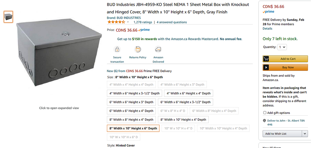
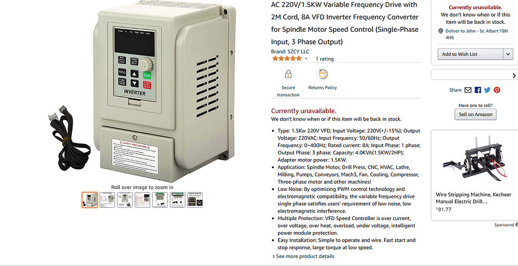
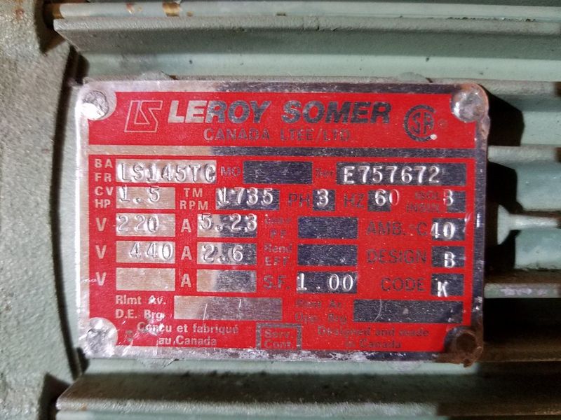
I don't know anyone who likes changing belts positions to change speed on a drill press. I cursed many times after drilling a 1/8" pilot hole then having to change belts positions for a 1/2" drill bit to finish the hole. I've had this project in mind for a while now and finally found great deal on a 1.5 HP three phase motor (thanks Chad).I bought an inexpensive 1.5KW (2 HP) vfd on Amazon as well as an electrical box to house it.


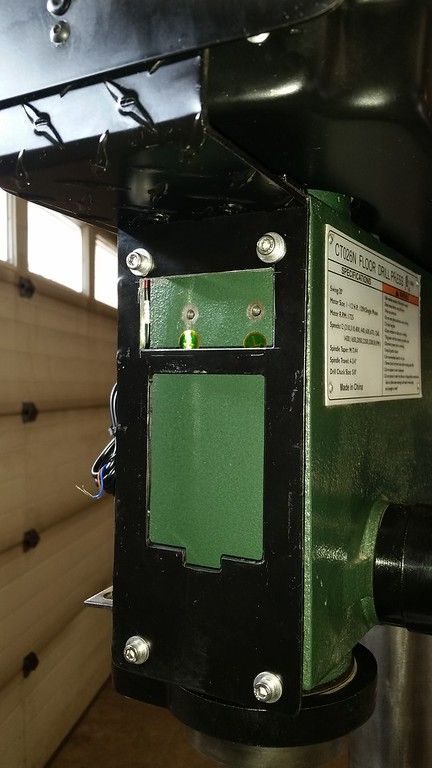
I made up a bracket from some 3/16" aluminum to hold the vfd, control panel and tachometer. I cut the rectangular holes for the panel and tach on the mill before I riveted the bracket parts together.


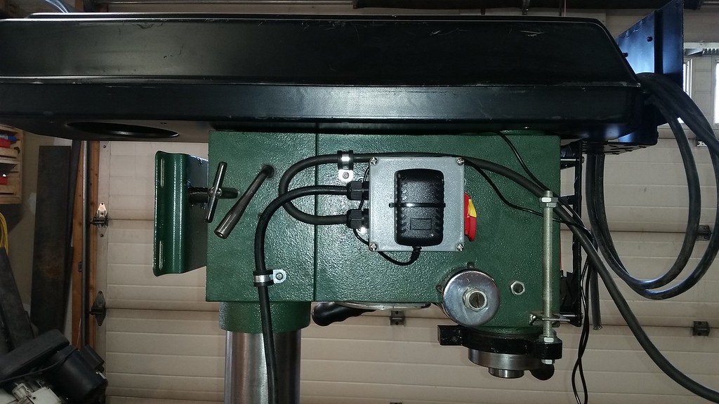
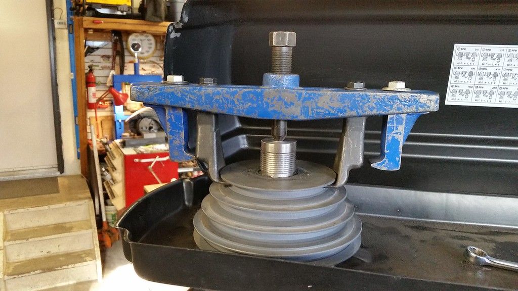
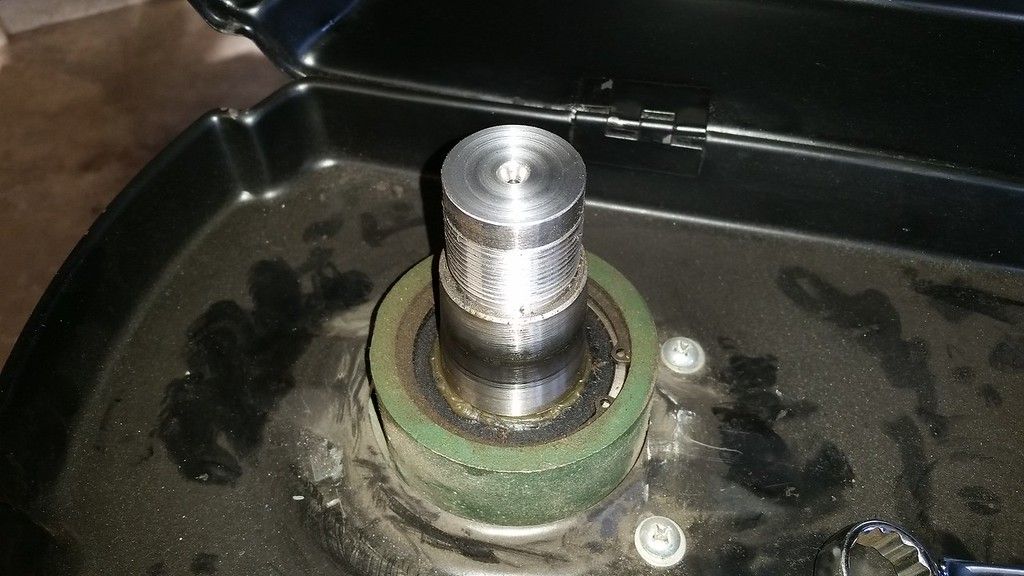
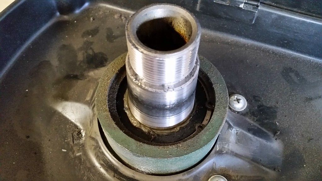
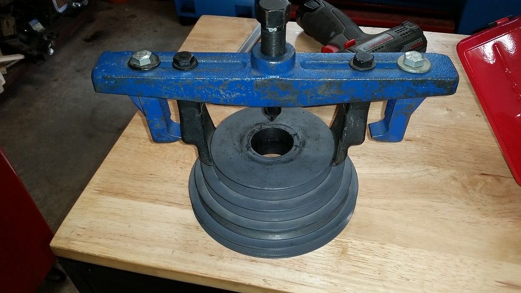
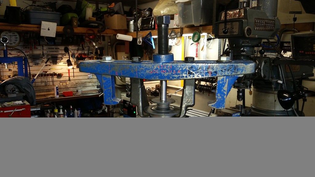
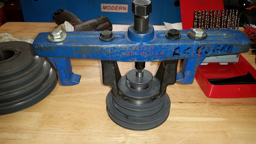
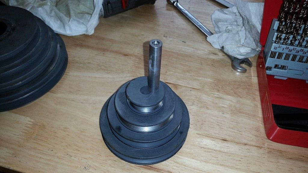
I removed the top belt housing along with the spindle, idler and motor pulleys. I used an automotive a/c compressor clutch puller to remove the motor and spindle pulleys. I had to machine a couple of pusher slugs to work with the puller.


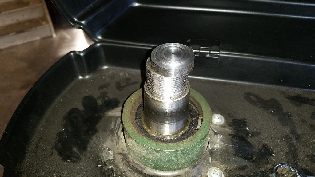
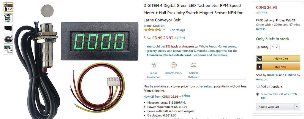
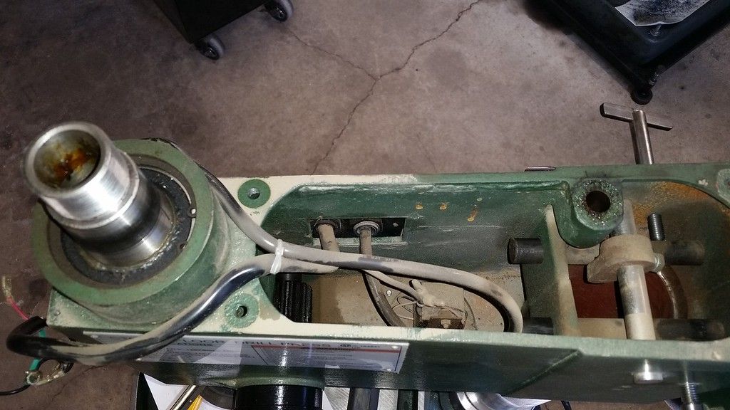
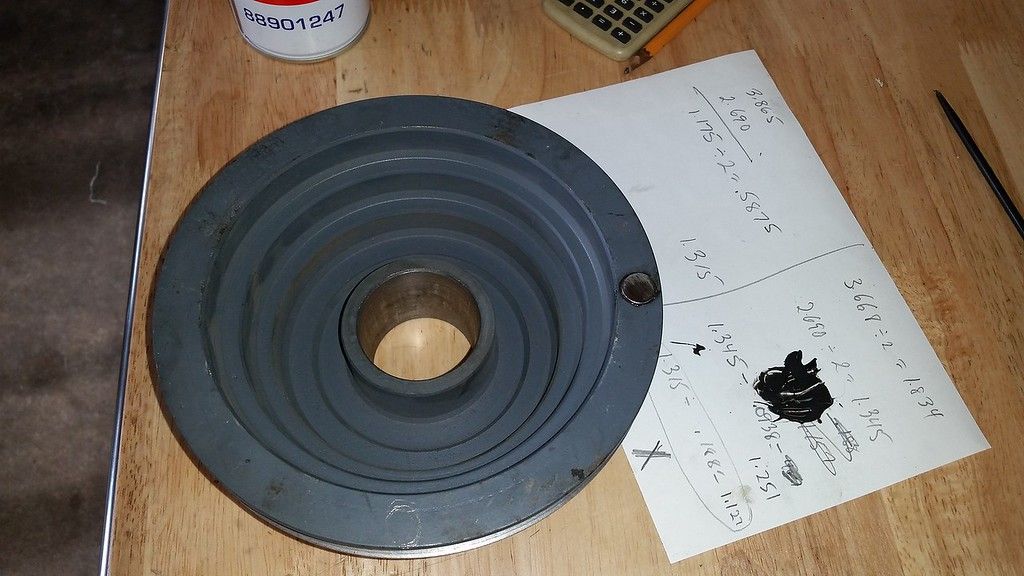
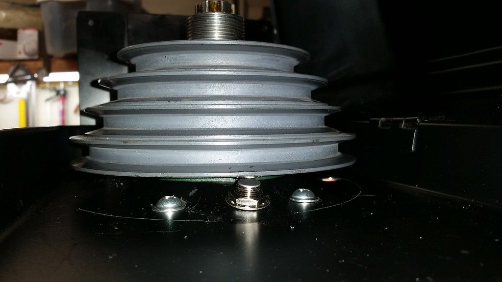
I mounted the tach magnet with epoxy to the bottom of the spindle pulley after milling a shallow pocket for it. I drilled a hole to mount the pick-up in the bottom of the belt shroud to align the pick-up with the magnet.


e.
 

John Conroy

member
Premium Member
I had to build a mounting bracket for the motor as it was designed to be face mounted. I used some 1/2" X 7" hot rolled plate left over from another project. A little overkill on the size of the steel but it was laying around. The motor has a 4.5" raised flange centered around the 7/8" shaft and a 4 hole bolt hole pattern. I machined the holes on the mill using the rotary table attachment on my 8" super spacer.


I mig welded the 2 parts of the bracket together. Outside welds done with both parts bolted to the motor and inside welds done with the bracket firmly clamped to the welding table. Amazingly the 2 parts were still at 90 degrees to one another when welding was finished.


I also welded the top 2 bolts to the bracket so it would be easier to mount the motor without fumbling with nuts and bolts. I painted the bracket black. It turned out well.


Last edited:

John Conroy

member
Premium Member
Since the new motor has a 7/8" (.875") shaft and the old one was 20mm (.790') I planned on just using a single groove pulley on the motor. After thinking about that for a while I decided I wanted the keep the multi groove pulley to allow for the maximum speed adjust-ability. Since I don't have any keyway broaches I did some careful measuring and found that the keyway in the pulley would still be deep enough to accept the key after removing .085" from the bore so I bored it on the lathe. I had to modify the pulley's 5mm key to fit the 3/16" groove on the motor shaft. I used the belt sander to make a .009" step on one side of the key.
I installed an led light where the original laser aiming gizmo was. That light and the tachometer needed a 12 volt source so I used a 12V wall wart power supply and hard wired it to the 240 volt single phase supply. I mounted that and the power switch in a 4" X4" X 2" plastic electrical box. The power supply fits through the outside of the cover and I used some insulated female terminals the fit over the make spades on the plug terminals.


The light is just glued (with clear silicone sealant) onto an 1/8" aluminum disc I cut out on my scroll saw.


I mounted the box and vfd above head height on the front as it seems like the best place to keep it out of harms way from getting banged up when rolling the drill press around or from chips. I used rubber covered stranded 14 gauge cable to wire everything, 3 conductors from the wall to the vfd and 4 from the vfd to the motor.


I set up the vfd with a maximum frequency of 120HZ and a minimum of 30HZ. In the belt position I will likely use the most the spindle runs at 330 rpm at 30HZ and 1330 rpm at 120HZ. I rarely used higher speed than that since most of my drilling is in metal. If I put it in the bull low belt position I can get 100 rpm at 30HZ so that will be good for large hole saws in metal.


It turned out well and I'm pretty happy wit the performance.
 
Last edited:

DPittman

Ultra Member
Premium Member
Another top notch project done by @John Conroy . Well documented and perfectly executed.

I have an ignorant question... someday I'd like to have vfd on my mill and/or drill press. Can one vfd controller be used for two separate machines if they have the same motor ? ( and obviously not used at the exact same time)
 

John Conroy

member
Premium Member
Thanks guys, I think I'll use the drill press alot more now.

[QUOTE=" Can one vfd controller be used for two separate machines if they have the same motor ? ( and obviously not used at the exact same time)[/QUOTE]


When I picked up the motor from Crosche he showed me a switch he uses to have 1 vfd run 2 tools. Maybe he will add some insight here.

Maybe a switch like this?

https://www.amazon.com/Baomain-Univ...eywords=3+phase+switch&qid=1614108117&sr=8-12
 
Last edited:

PeterT

Ultra Member
Premium Member
Nice work John. I was toying with a conversion myself to 'learn' VFD but some of the disassembly & new mounting issues made me think it wasn't going to be quick job.
Were the motor sheaves difficult to remove with the puller?
Was the different shaft diameter more a function of the larger motor you selected or maybe IMP/MET thing? My drill is Taiwan which I assume is metric but never actually measured it.
btw - you probably know but I discovered - chamfering & counterboring work MUCH better at tickover low rpms. I could'nt figure out why I was getting weird chatter looking maks on the drill press but not on the mill. The DP was just not low enough.
 

John Conroy

member
Premium Member
The spindle pulley fits onto a taper on the spindle. The nut on top of the pulley is left hand thread but is only made of plastic. Once I got the nut off and made the pusher slugs it didn't take much force to remove either pulley but I think a puller is needed. There is not good place to pry under either pulley. If you need a puller I can lend you one.

The different shaft sizes are because the 3 phase motor is made in Canada and the single phase one made in China. I ran into the same thing when I changed the motor on my lathe. The pulley is cast iron and machined very easily. My final pass with the boring bar was a spring pass and the result was a fit .0005" tighter than the Princess auto pulley I was going to use. I used my heat gun to warm up the pulley so it was too hot to touch and it dropped right onto the motor shaft easily. Now it was too far on and I had to use the puller again to pull it back up the shaft to get the pulleys aligned before tightening the set screw.

Yeah I have found that the chamfering and countersink tools like to be used at very low speed. I should be able to use them now on the drill press since it can now go much slower. I think most drill presses can't go slow enough. The speed range on mine originally was 210 rpm to over 3000 rpm. I'm not sure why you would need such a high speed. drill press speeds.jpg
 

CalgaryPT

Ultra Member
Vendor
Premium Member
Since the new motor has a 7/8" (.875") shaft and the old one was 20mm (.790') I planned on just using a single groove pulley on the motor. After thinking about that for a while I decided I wanted the keep the multi groove pulley to allow for the maximum speed adjust-ability. Since I don't have any keyway broaches I did some careful measuring and found that the keyway in the pulley would still be deep enough to accept the key after removing .085" from the bore so I bored it on the lathe. I had to modify the pulley's 5mm key to fit the 3/16" groove on the motor shaft. I used the belt sander to make a .009" step on one side of the key.
I installed an led light where the original laser aiming gizmo was. That light and the tachometer needed a 12 volt source so I used a 12V wall wart power supply and hard wired it to the 240 volt single phase supply. I mounted that and the power switch in a 4" X4" X 2" plastic electrical box. The power supply fits through the outside of the cover and I used some insulated female terminals the fit over the make spades on the plug terminals.


The light is just glued (with clear silicone sealant) onto an 1/8" aluminum disc I cut out on my scroll saw.


I mounted the box and vfd above head height on the front as it seems like the best place to keep it out of harms way from getting banged up when rolling the drill press around or from chips. I used rubber covered stranded 14 gauge cable to wire everything, 3 conductors from the wall to the vfd and 4 from the vfd to the motor.


I set up the vfd with a maximum frequency of 120HZ and a minimum of 30HZ. In the belt position I will likely use the most the spindle runs at 330 rpm at 30HZ and 1330 rpm at 120HZ. I rarely used higher speed than that since most of my drilling is in metal. If I put it in the bull low belt position I can get 100 rpm at 30HZ so that will be good for large hole saws in metal.


It turned out well and I'm pretty happy wit the performance.
Wow, you put your heart into that mod. Great job John. Super nice work. That's one of those mods you first read and think, "that's totally unnecessary and expensive and way too much work." Then by the end of the thread you're thinking, "that's absolutely essential, I don't care how much work or how much the parts cost, I have to have that." Great work John....I'm looking at my drill press strangely right now. Congrats.
 

John Conroy

member
Premium Member
Thanks Pete, it was a lot of work but fun work. I'm pretty bored with isolation so I'm always looking for a project. I got the motor for $40 and the rest of the stuff including the cable was about $250. Not cheap but I only paid $300 for the drill press so I think it was worth it.

There is quite a bit of info online about these cheap vfd's. The model is XSY-AT1 and people seem to like them. This one is rated for 2hp and the motor is 1.5 so I hope it lasts.
 
Last edited:

DPittman

Ultra Member
Premium Member
I wish I could have had you make duplicates of all your parts while you were at it....I have the exact same drill press. I didn't realize a 3 phase motor could be had for $40...was that a rare deal?
 

John Conroy

member
Premium Member
I got the used motor from Crosche here in the forum classifieds. It was not ideal for this use as it only had mounting holes for face mounting, no mounting bracket. I was almost ready to order one from EMotors Direct but $280 for a TEFC (totally enclosed fan cooled) motor from them. I would not have needed to make the mounting bracket if I bought this motor.

TECO Rolled Steel TEFC_motors.jpg

I figured it was worth a couple of hours work to make the bracket since the motor was a good deal and I already had the steel. You can probably find a used one on Kijiji or maybe Tom Kitta has one.

https://www.emotorsdirect.ca/item/teco-rf1-54

I bought a new 3 HP motor from them for my lathe.

https://www.emotorsdirect.ca/item/teco-pdh0034


There is one listed on Amazon for $213

https://www.amazon.ca/Hallmark-Indu...ords=1.5+electric+motor&qid=1614117088&sr=8-6
 
Last edited:

ShawnR

Ultra Member
Premium Member
Very nice John! Thanks for posting and the documentation!

I have acquired a few treadmill motors and figured out the controllers yesterday. I have been wanting to do a similar conversion on my drill press too. You may have inspired me.
 

YotaBota

Mike
Premium Member
Being able to remote the vfd control panel is a nice feature.
Where did you get the 220v wall wart?
 

YotaBota

Mike
Premium Member
I forgot about dual voltage warts, I may replace my battery with one.
Thank you sir.
Edit - after going to the link I realized that I have basket in the closet with old warts in it and AHA, there are a couple of 12v dual voltage units in the basket. Now I'll be able to put the battery back in the box with the drill.
 
Last edited:
Top