• Spring 2024 meetup in Calgary - tentative date Saturday, April 20/2024. Other regions are also discussing meet ups. If you want one in your area get going on organizing it! discussion
  • We are having email/registration problems again. Diagnosis is underway. New users sorry if you are having trouble getting registered. We are exploring different options to get registered. Contact the forum via another member or on facebook if you're stuck. Update -> we think it is fixed. Let us know if not.
  • Spring meet up in Ontario, April 6/2024. NEW LOCATION See Post #31 Discussion NEW LOCATION

Circuit

PeterT

Ultra Member
Premium Member
Ok, this should provide lots of comedic entertainment to electrical savvy guys. Apparently I am not qualified on the most basic of circuits.
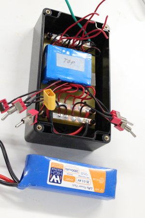
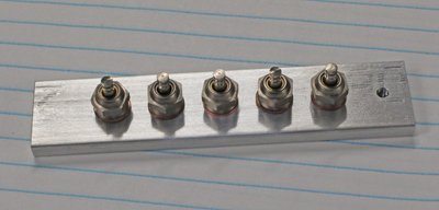
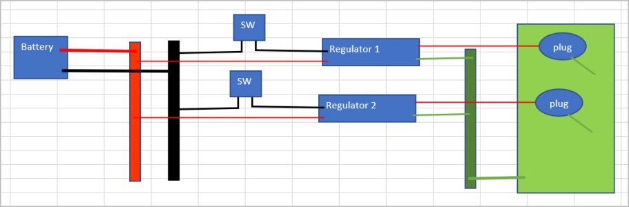
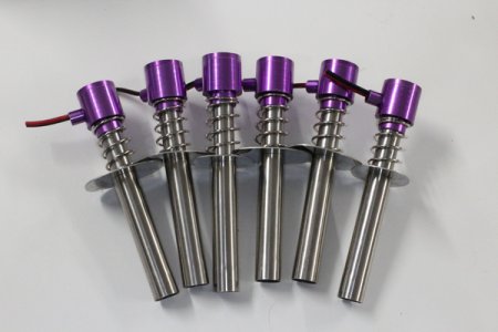
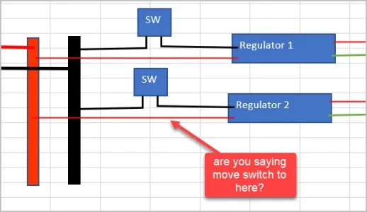
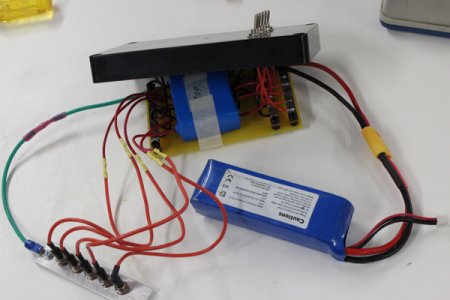
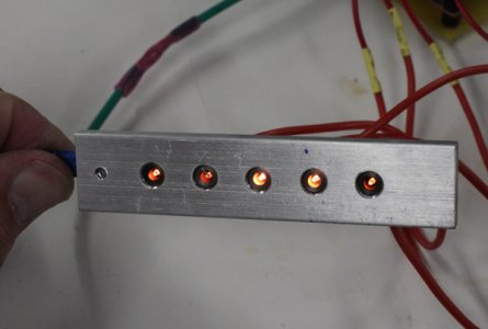
This is my glow plug ignitor box work in progress & mockup strip holding 5 glow plugs. I have 5 voltage regulators in parallel & switch dedicated to each plug (at least that was my intent).
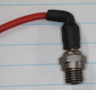
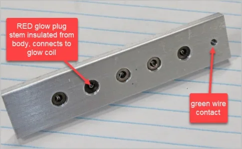
The red wire from regulator is connected to glow plug stem. Stem is insulated from body, goes to glow coil. The plug body/threads/aluminum dummy strip are ground.

The issue is when I flick a switch, they all light up. WTF? At least the magic smoke stayed in :/
 

Attachments

  • IMG_5019_edited-1.jpg
    IMG_5019_edited-1.jpg
    419.1 KB · Views: 14
  • IMG_5020_edited-1.jpg
    IMG_5020_edited-1.jpg
    81.9 KB · Views: 15
  • IMG_5003_edited-1.jpg
    IMG_5003_edited-1.jpg
    210.2 KB · Views: 14
  • SNAG-2022-11-05 4.05.07 PM.jpg
    SNAG-2022-11-05 4.05.07 PM.jpg
    71.4 KB · Views: 15
  • IMG_5012_edited-1.jpg
    IMG_5012_edited-1.jpg
    185.2 KB · Views: 16

phaxtris

(Ryan)
Premium Member
Premium Member
Your grounds probabaly (should be) connected together somewhere. Switch the hot, not the ground
 

PeterT

Ultra Member
Premium Member
Not sure if I'm using 'ground' word properly but maybe this helps explain.
When you say move the switch, like so?
 

Attachments

  • EDT-2022-11-05 5.49.06 PM.jpg
    EDT-2022-11-05 5.49.06 PM.jpg
    42.1 KB · Views: 8
  • EDT-2022-11-05 5.53.24 PM.jpg
    EDT-2022-11-05 5.53.24 PM.jpg
    45.5 KB · Views: 8
  • EDT-2022-11-05 5.54.47 PM.jpg
    EDT-2022-11-05 5.54.47 PM.jpg
    47.2 KB · Views: 8

phaxtris

(Ryan)
Premium Member
Premium Member
Yes move the switch to the positive line (red), I'm out atm, but I'll explain in 20min when I get home
 

phaxtris

(Ryan)
Premium Member
Premium Member
@jcdammeyer has got it for you

how you had it when you switched one regulator on you were completing the ground circuit for every regulator, as the grounds are all tied together after your switches, including everything on all of the boards, so power was able to flow through your switch to every ground, and back to the battery through the positive's as they were already connected to positive

as a general rule in dc circuits you typically switch the positive as grounds are generally tied together
 

PeterT

Ultra Member
Premium Member
Thanks guys. I actually started out the way you show with switch between regulator & glow plug. But when I tested a single module, I noticed a little LED light came on inside the reg when I first connected the battery but not yet the glow plug. Because the glow plugs are only one for say 30 secs to start the engine, then off for say 10 min while running, I wasn't sure if it was good for the regs to be 'on' for this duration. Not really sure if it hurts them or draws much power but that's why I put it on the 'in' side so reg would see now power at all. Is this still an option & I just happened to pick the wrong wire for the switch?

1667699979245.png
 

jcdammeyer

John
Premium Member
Thanks guys. I actually started out the way you show with switch between regulator & glow plug. But when I tested a single module, I noticed a little LED light came on inside the reg when I first connected the battery but not yet the glow plug. Because the glow plugs are only one for say 30 secs to start the engine, then off for say 10 min while running, I wasn't sure if it was good for the regs to be 'on' for this duration. Not really sure if it hurts them or draws much power but that's why I put it on the 'in' side so reg would see now power at all. Is this still an option & I just happened to pick the wrong wire for the switch?

View attachment 27675
Just move the switches so they break the green trace instead of the red trace. As @phaxtris mentioned since the grounds and the outsides of the glo plugs are common (often called ground) you don't want to switch those.

Like this:
 

Attachments

  • GloPlugs.pdf
    98.7 KB · Views: 3
Last edited:

PeterT

Ultra Member
Premium Member
Your grounds probabaly (should be) connected together somewhere. Switch the hot, not the ground

Maybe you saying this, if red OUT is hot to the plug, then red IN is likely hot & thats where I should have put the switch?
 

Attachments

  • EDT-2022-11-05 8.16.54 PM.jpg
    EDT-2022-11-05 8.16.54 PM.jpg
    46.6 KB · Views: 3

jcdammeyer

John
Premium Member
Maybe you saying this, if red OUT is hot to the plug, then red IN is likely hot & thats where I should have put the switch?
Yes. See my latest GloPlugs.pdf just before this message. Guess I should probably add revisions to the schematic names.
 

phaxtris

(Ryan)
Premium Member
Premium Member
Maybe you saying this, if red OUT is hot to the plug, then red IN is likely hot & thats where I should have put the switch?

exactly, well sort of....electrons actually flow from negative to positive, but the way dc circuits are designed the common/ground/negative/black is typically tied together so the control is with the positive/hot wire, not with the ground/neg/common/black......at least in basic circuits

and you are right, you would want the switch in positive before the regulators in a battery application...it wont hurt the regulators, but there will be some small current draw wich could eventually drain the battery
 
Last edited:
Top