• Scam Alert. Members are reminded to NOT send money to buy anything. Don't buy things remote and have it shipped - go get it yourself, pay in person, and take your equipment with you. Scammers have burned people on this forum. Urgency, secrecy, excuses, selling for friend, newish members, FUD, are RED FLAGS. A video conference call is not adequate assurance. Face to face interactions are required. Please report suspicions to the forum admins. Stay Safe - anyone can get scammed.

Check my thinking please!

DavidR8

Scrap maker
Administrator
Moderator
Premium Member
Hoping folks can check my thinking.
The X axis ball screw that came in the kit I bought is too long for my table so I need to cut it down and machine the end.
I don't want to mess this up.
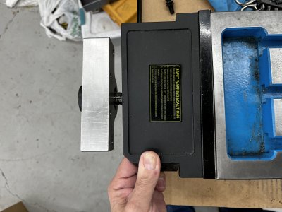
Here's some pics to illustrate the situation.

Here the excess length and the machined end.
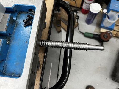
IMG_1925.jpeg

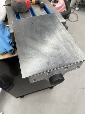
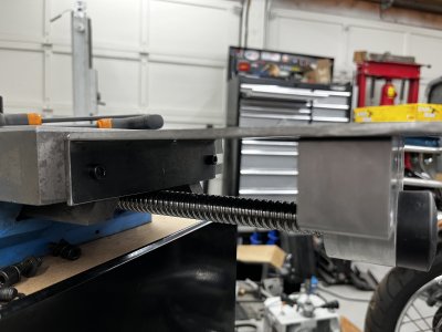
This is the bearing carrier and the mount that screws onto the end of the table.
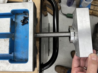
IMG_1926.jpeg

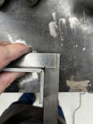
I measured the distance between the end of the table and the mount and came up with 130mm.
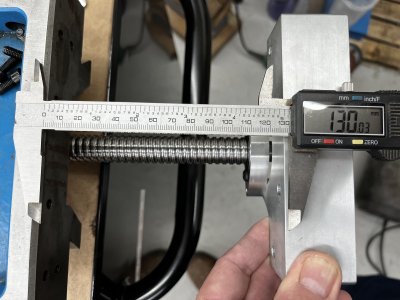
IMG_1927.jpeg

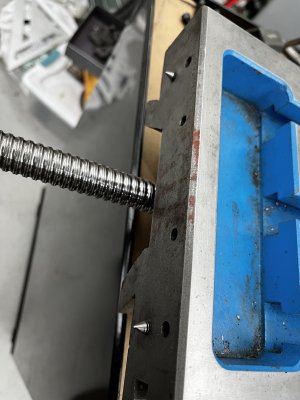
This is what 130mm looks like on the ball screw.
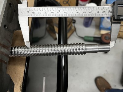
IMG_1928.jpeg

So my thinking is if I cut off 130mm of length then machine then machine the features on the end, the mount should bolt up to the table. For good measure I may make the bearing surface a smidge longer to make sure the mount seats well on the end of the table.

Is my thinking correct or am I overlooking something obvious?
 
Most pre-machined ball screws have the other end machined with a snap ring groove, might be easier to machine the other end. The outer skin of the metal is hard but the interior is relatively softer. Have machined quite a few for our mini-mills.
 
It’s similar to machining IHC or chrome plated materials. That first cut ideally is such that you get ‘under’ the outer skin. In a pinch some grinding to get rid of the bulk of the hard stuff first may be easier if you have a small/light machine to do this with.
 
Most pre-machined ball screws have the other end machined with a snap ring groove, might be easier to machine the other end. The outer skin of the metal is hard but the interior is relatively softer. Have machined quite a few for our mini-mills.
Unfortunately, the other end end has a threaded end for a nut. So this end seems like the easier one to modify.
 
It’s similar to machining IHC or chrome plated materials. That first cut ideally is such that you get ‘under’ the outer skin. In a pinch some grinding to get rid of the bulk of the hard stuff first may be easier if you have a small/light machine to do this with.
My plan was to heat the area where the cut needs to be made and back where the features need to be machined.
 
Is it feasible to make an extension? Might not be the most compact but it would work and you would not have to cut the ball screw down.
 
Is it feasible to make an extension? Might not be the most compact but it would work and you would not have to cut the ball screw down.
It’s possible, it would have to be pretty beefy to support the servo hanging off the end and resist the rotational forces.
On further reflection the extension could go at the other end of the ball screw where there’s no servo hanging off.
 
Last edited:
On further reflection the extension could go at the other end of the ball screw where there’s no servo hanging off.

NICE!

I LIKE THAT!

With a little effort, that extension could become someplace to put your essential mill tools and other things that need a surface or assorted hangers to keep them handy!

Lots of beefy support there too. I like it!
 
+1 on the extension. The extension shouldn't need any more than 1/4 or 5/16 plate on the non servo end. It's only 5"ish but as @Susquatch says, it would also give more surface to pile tools on.
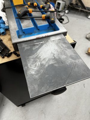
Interestingly enough, the distance is probably really close to the distance the old power feed is held away from the end of the table by the mounting bracket.
Pics to follow.
 
Well that worked out just perfectly.
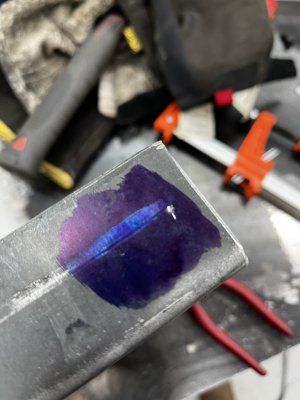
Made some 6mm transfer screws.
IMG_1932.jpeg
Lined it all up and marked it.
IMG_1933.jpeg
Drilled the holes and installed it.
IMG_1934.jpeg
IMG_1936.jpeg
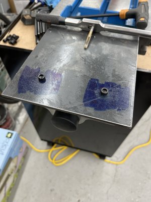
Now to mark the holes to secure the ball screw mount.
And done. Need some round head M6 cap screws for a cleaner job.
image.jpg
 
Last edited:
I tried to camouflage the real purpose for @DavidR8 but you guys saw right through me!

Nothing beats a horizontal surface for keeping things visible and ready to go!
The mill will be inside an enclosure so the potential for this to be tool storage is minimized :D
 
Back
Top