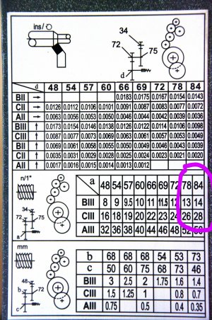
You can see in my lathe threading chart that I need to have a 78 tooth "a" gear to make 26tpi and a 84 tooth "a" if I want to do 28tpi. Would a 81 tooth "a" make 27 tpi? Is it as simple as that? ( I don't actually have a 81t gear but could make one)
I've wondered about further threading possibilities with my lathe but I can't comprehend the necessary math and formulas to extrapolate.
If you look at the thread chart, and know the lead screw pitch, its possible to determine the actual gear ratio of each position of your qcgb
for example, your first row is 8/16/32, second is 9/18/36 - and so on, but theres the change gear ratio before the qcgb, so with some math, tons of feeds and thread pitches are possible that arent listed
This <might> help, but without knowing how the upper 5 gears relate to the lead screw it's hard to do the calculations. Are all the upper five gears the same number of teeth? The sketch implies the first and fifth gear are the same, and the three centre gears are the same. If this is true, or if all five are the same, then the calculator will work as the upper five gears are just there to allow changing the lead screw directions and will have no effect on the feed screw/headstock relationship.
Make a list of all the change gears you have, then:
Thanks for that I will attempt to understand that.
I believe the top two gears in my diagram are from the reverse tumbler mechanism and I don't believe changing the direction of the lead screw affects the ratio at all.
I have 16 different gears.
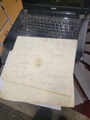
With a 16tpi leadscrew, to make a 27tpi thread, the spindle needs to rotate 1.6875 times for each revolution of the leadscrew. The rest of the math depends on the rest of your gear train.
If my math is correct, for 26tpi you have a 2.3897:1 ratio in the gears, and 0.68:1 in the qcgb giving you 1.625 turns spindle, to 1 turn leadscrew. Knowing that, by substituting and 81 tooth gear gives you 1.6870841529 which is pretty close to what you need for 27tpi
If my math is correct, for 26tpi you have a 2.3897:1 ratio in the gears, and 0.68:1 in the qcgb giving you 1.625 turns spindle, to 1 turn leadscrew. Knowing that, by substituting and 81 tooth gear gives you 1.6870841529 which is pretty close to what you need for 27tpi
Ok so you did it the right way, I just looked at a chart and said a thread in between two others must need the leadscrew gear also in between. Was that just luck on my part?
Just figured out what ratio it was with 26tpi, then subbed the 81 tooth gear for 27tpi. And a bunch of chicken scratch math that will make no sense to anyone else. Anyways you will end up at 26.99tpi
Just figured out what ratio it was with 26tpi, then subbed the 81 tooth gear for 27tpi. And a bunch of chicken scratch math that will make no sense to anyone else. Anyways you will end up at 26.99tpi
so, I like figuring these things out, so i did the math to confirm some numbers, just for fun, and to help anyone who might want to know this for their lathe
B111 ratio is 0.34:1 - input (change gear side) to output (leadscrew)
C111 ratio is 0.68:1 (see the relationship between these numbers?)
A111 ratio is 1.36:1
So to figure out for 27tpi, with a 16tpi leadscrew, the spindle must turn 1.6875 turns per 1 leadscrew turn (27/16=1.6875)
first change gear ratio: 34:75 = 2.2059:1 (always divide the driven by the drive gear teeth number)
second change gear ratio 72:81 = 1.125
final compounded change gear ratio = 2.4816375:1 (2.2059x1.125)
2.4816375 (change gear ratio) x 0.68 (C111 qcgb ratio) =1.6875135 (spindle turns per turn of leadscrew)
thats pretty close i'd say. Who said math isn't fun?
It's fun when brainiacs do it 4 U! Awesome awesome awesome. Im going to have to SLOWLY work through that and try a few calculations myself. Thank you for the help.
It's fun when brainiacs do it 4 U! Awesome awesome awesome. Im going to have to SLOWLY work through that and try a few calculations myself. Thank you for the help.
I had similar frustrations with the threading and feed charts on my first lathe (a House of Tools 12x36 FRV 30-GL300C). there was at least one error on the charts, and I was never really quite sure of what change gears were required to do what, or what all the possible feed and threading possibilities were since only a small subset of the possibilities are listed on the faceplates.
The lathe had a few external change gears, an MI/MII range lever, an A through E gear lever, and a 1 through 5 gear lever to set the internal gears that drove the lead screw and feed shafts.
So, I did some measuring to figure out what was in the internal gearbox, and built a spreadsheet to generate the true and complete feed rates and thread pitch tables.
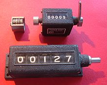
I started out by digging up a couple of mechanical rotation counters from my hoarding stockpile. Something like these.
I mounted one in the chuck (easy) and the other at the end of the lead screw. I think I used a magnet and some glue to mount to the end of the leadscrew. Later, I did the same thing with the feed shaft.
I then ran the lathe through a couple of hundred chuck rotations in each gear setting (with one fixed set of external change gears), and logged the results in a spreadsheet.
"A-E" and "1-5" are the two gear setting handles on the lathe. With a little bit of guessing, from the calculated ratio of the chuck : leadscrew I figured out what the real internal gear ratios were for each gear setting.
Some were easier to guess at than others. The easy ones are listed above. I then made some more sub tables in the spreadsheet to look at the ratios for just the A-E changes and the 1-5 changes when I normalized one of the ratios to 1:1, which gave me the ratios that each gear lever accomplished:
This did not tell me the actual number of teeth in the internal gears, but left me about 99.9999% sure of what the exact tooth ratios were for each gearbox setting. There was another setting: MI/MII, but that was easy, it was a simple 1:2 ratio.
I have attached V1 of my lead/feed calculator for further analysis of it it helps anybody. The two tables above are from this spreadsheet.
If there is interest, I can post the final version of the spreadsheet that created nice tables of all the lathe settings, and what I did to figure out the same stuff for my replacement Colchester-style knock off - which uses a very common type of feed gearbox (using levers often labeled: C-D-E, R-S-T, W-X-Y-Z, and 1 through 8) that does not generally require any change gears for metric or imperial threads.
I have found having this data to be invaluable to using the lathe.
So above we figured a 81 tooth gear would allow me to cut a 27tpi. "Great" I said " I have no need to cut a 27tpi and I don't have a 81 tooth gear either but I could make one just in case!"
I figured this would give me the opportunity to try out my never used dividing head and my never used gear cutting skills on my milling machine. So I figured out the dimensions needed for a gear blank and got the appropriate chunk of steel. I then started to refigure out how to use a dividing head. It appears that 81 divisions are not possible with the dividing head (at least with mine it isn't) Am I missing something or am mistaken?
It depends on the ratio of the dividing head and which dividing plates that you have on hand. If you bought a complete kit with all the plates, its definitely possible
Edit, i just looked it up and apparently an 81 tooth gear IS a problem with a 40:1 dividing head....
Ok I was just basing my conclusion on the charts that came with the dividing head. I believe there are 3 separate plates. (I'm not in the shop right now so I can't confirm) My diving head has 40:1 ratio