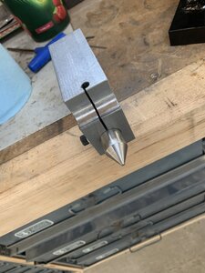
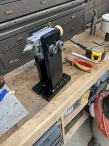
Building a tailstock for a 12” Rotary table

Brent H

Ultra Member
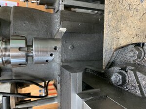
So this one is needed so I can support the mandrels better when making gears. I have some cutting to do on a longer shaft so this project is a must.
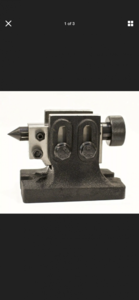
This is a small one for a 4” rotary table:

FBA1B398-62CD-4E3B-B615-2DAD0A5BB529.png
I you could just add some water and it would expand - that would be sweet! But no .....
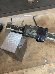
The parts are coming from a heavy piece of angle I torched up and the centre holder part is from a piece of the hull (bow section) of the ship I work on. We installed a new bow thruster in 2016 so this chunk has been in the “future plans” section for a while - LOL. It is Grade E steel which means it is supposed to retain its properties down to -40° C. Ice breaking -LOL

5A40E111-3207-4D4C-B09D-309BA44BC226.jpeg
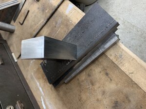
Here is the pile of other steel:

38CE9955-A293-4820-B010-20089A1B198F.jpeg
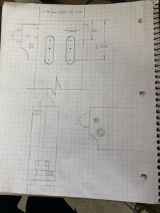
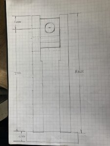
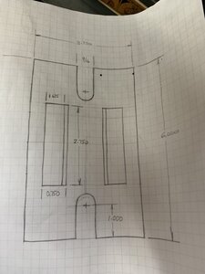
Here are the very rough plans - still jigging them a bit:

4B174061-04B9-4FCC-A574-7D740562D6CA.jpeg C8135599-84C3-451A-B364-7F270386731C.jpeg
And the base:
004AC108-5A49-4C6E-B00B-705D8FC15467.jpeg
I got a good start on it today - will post more after I make the dinner ......
 

Tom Kitta

Ultra Member
I almost build what you are planning to build - then I realized that I can use simply re-use an existing tailstock I had for a indexing head. Note that this is not the only design you can copy. It is probably one of the easier (but not easiest) designs through. I ended up making from the parts a wheel balancing fixture - i.e. static balancer.

Easier design would be one without adjustment up or down as an example.

Note that this will not really support mandrels well while cutting gears - what I used was a machinist jack right under the area being cut - unless the shaft you are cutting is really thick.
 

Brent H

Ultra Member
The shaft is 1-1/4” plus a few other things to machine.

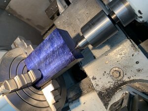
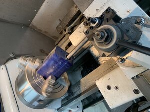
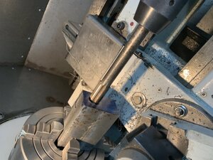
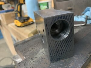
I mounted and centred the big block in the four jaw and then proceeded to drill it out to size. The hole is to be 3/4” so I drilled up in steps - 2 of the few #2MT bits missing in my set is the 23/32 and the 47/64th so I hade to change things up and bore the last few thou and then reamed to 3/4.
FBFBAB8D-1862-4BF7-B42F-B20189A5F0F8.jpeg
5374D1AD-44F9-4C3C-BEFE-ED0C7AFD9E2D.jpeg
540A48F8-7B8F-465A-A382-4A84665F8D94.jpeg
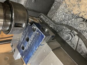
The. It was back to the mill for all the holes and threads.
0FE7FCF4-4A23-41E3-9F79-10B5D6404123.jpeg
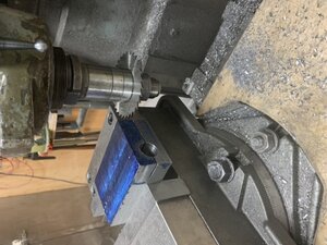
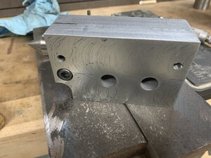
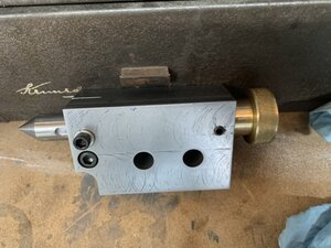
1/16 slot cut to allow tightening up the centre

62D76454-2D72-4828-B575-16B3B18B5B74.jpeg
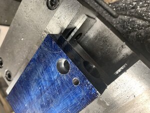
Holes for the set screw that keeps the centre from spinning when advancing it and the counter bore for the 5/16 socket head cap screw that locks the centre

DE9B0252-9C06-4365-BFD8-3FB1C5474060.jpeg
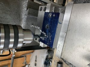
drilling out the holes for the 1/2” bolts that will hold everything in place.
9711CB87-3153-4F70-8826-BC25ED86E61D.jpeg
Milling out the bottom relief (3/4” end mill)

A918FAB9-6D86-4A22-9198-252E655A3242.jpeg
B90A9040-434E-4B18-BDEF-4B3F5D475057.jpeg
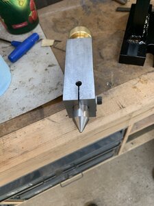
above pic is the back of the block. This will house the adjustment to dial in and out the centre - the centre is a piece of 3/4” round stock (pretty hard so like a 4130). The centre is drilled out to 2.5” and tapped to 7/16-20

54E0346A-7676-4A4B-B573-4D4DE2C4B5E3.jpeg
That’s where I am today. Will be making a few brass items and the base part as soon as possible.
 

PeterT

Ultra Member
Premium Member
You are a speedy builder, Brent.
When you do slitting/sawing like that, do you cut in progressively deeper passes, or one shot & just adjust the feed accordingly?
 

Brent H

Ultra Member
I just let’er rip @PeterT - full depth and feed to avoid vibration, squeaks and other noises. As I have no power y axis it is hand driven - watch the chips and the heat - I try feed so it sounds like a clean cut and chips come out not burnt - cutter was HSS - applied oil as the slice progressed.
 

Brent H

Ultra Member
Slitting saw was 3” diameter, 1 inch bore, 36 tooth HSS at 95 RPM and feed rate as per me. I would think it took me 5 minutes to slice 2-1/5” ...... maybe 8 minutes. Added lube to start - my lathe takes 30W detergent free so I have several oil cans loaded with that as .... well you can squirt different places in the lathe so that is my lube ....
 

Brent H

Ultra Member
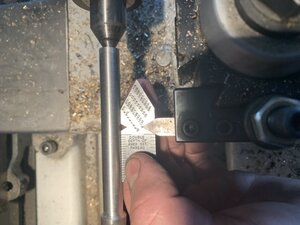
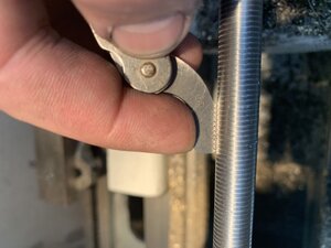
Some lathe work today. Turned a 9/16” piece of 4140 down to 7/16 (0.4375) and then threaded it to 20 TPI. About 3” worth of thread for the adjustable centre.
A01C9BAC-70E7-4501-A368-BF8E28EA7D42.jpeg
1A239CEE-7076-41D4-9533-8B7336620243.jpeg
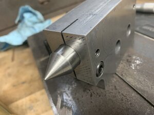
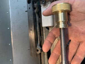
Also made up a brass knob end for the screw. This fits the block and allows you to turn the centre in and out. The brass is 1” round stock and I shrunk fit the larger knob on (0.002” interference fit). Knurled the knob with a straight type knurling tool. Will have to work on that technique as it is a load on a little lathe.
BB5C5154-6B2C-4ED2-B038-DAA6526EE27D.jpeg
B94B258F-C25A-472D-8705-9636B2169BDD.jpeg
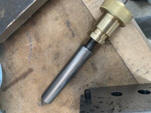
I machined a 1/4” wide by 0.125” deep slot in the centre to allow it to go in and out. So this is the centre assembly:

28A6B692-362D-44EE-8CBC-92B9C688848E.jpeg
Here is a mock up of the base - still need all the machining.
CB547447-929D-4344-8F10-85F6ABC74025.jpeg
Burgers and beer now :)
 

Brent H

Ultra Member
Ahh the saga continues.....

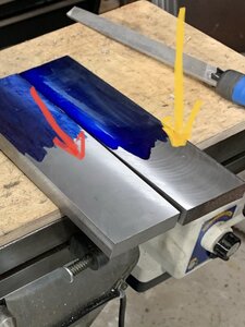
I missed a bunch of stuff as I was taking pictures and measuring for @YotaBota for the taper attachment on the Utilathe - anyway I surfaced the plates I needed to using a fly cutter - the first go was with a high speed steel cutter but I switched out to a carbide tipped cutter and it made for a nicer finish.
12A4C5D2-8DB8-407C-B1F2-8D598D9FDC29.jpeg
That pic is with the high speed steel cutter the fly cutter had in it.
Yellow arrow is the carbide and the red is the high speed steel.
A25BEFAA-26D5-40FA-B292-F69B1A288807.jpeg
Feeds and speed being about the same 600 RPM 10 to 20 thou depth of cut and reasonably quick speed over the part.

time warped and I just went at it so pictures are of it just needing some clean up

2B086BF6-947E-464D-A5DC-1091664DFFC5.jpeg
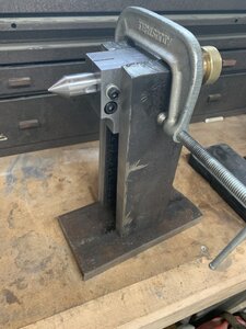
And then got welding ......

BDDD08AE-F998-4710-B46C-CDEDA7B825C9.jpeg
2C48E1A4-B023-4C8E-B7BD-FE9E3C689930.jpeg

tomorrow may be some paint for the base and sides :)
 
Last edited:

DavidR8

Scrap maker
Administrator
Moderator
Premium Member
Nice work Brent... how did you weld between the two uprights???
 

Brent H

Ultra Member
@David_R8 - I have a large 250 amp torch and a smaller 150 amp one. The smaller one allowed me to weld just from about 1/2 way on either side.

when I started the welding I was going fast and was distracted a bit by helping my son change his winter tires - totally gapped that I had a roll of stainless in the machine - Argh!! Was absolutely sh...tie to start and things did not look nice. Had to grind off the tacks carefully and then change out wire.

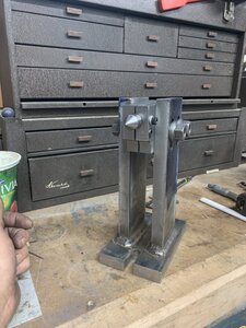
to help keep things straight I cut a 1/16” deep pocket that the side fit into so they maintained proper alignment and spacing. I did have some shrinkage as things cooled so I skimmed the centre holder for a better fit. It is snug but moves about reasonably well.
 

YotaBota

Mike
Premium Member
I missed a bunch of stuff as I was taking pictures and measuring for @YotaBota for the taper attachment on the Utilathe
Sure,,,,,,, blame the old guy half way across the country,,,:D lol.
Looks good though. What is the relief reliefing around?
 

Brent H

Ultra Member
Hey @YotaBota I posted plans for the Utilathe taper attachment - will be an epic project should you so choose - To which relief are you referring too?
 

Brent H

Ultra Member
@YotaBota - I think you are referring to the bolt slots for holding the whole thing down to the mill table. Those are 9/16” for 1/2” hold downs and are 1.282” long.
 

Brent H

Ultra Member
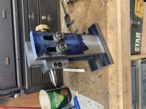
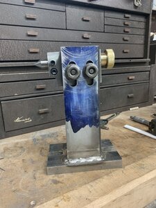
@YotaBota - that relief is to take out some of the steel so the Allen screw can clamp the centre in position easier. Adds some decoration as well. I can grab a few more pics tomorrow. The base is painted and drying.
 

Brent H

Ultra Member
Here are some additional pics - you will note the relief in the bottom the drill did not go straight - it was a cheap bit and wandered on the way through. Went fine on top 1324BBE5-C02D-469B-8FEA-1D14A2AF45CF.jpeg
113E69E1-9330-45C3-B09D-05962053E782.jpeg
C3C9C8A3-0CC1-4473-BC82-72720D14EBE8.jpeg
 

RobinHood

Ultra Member
Premium Member
Looks really nice @Brent H, well done.

I think the reason for the drill to wander off center was because it was in an interrupted cut - not so much because it was “cheap”.

Two ways to mitigate:

a) drill first, cut slot into the drilled hole second
b) insert a piece of sacrificial metal of the same type in the slot and clamp it. Then drill.

Both ways, the drill no longer has an interrupted cut.

I guess a third way would be to use a long enough, center cutting end mill; it would not care so much about the slot (interrupted cut) and probably go straight through.
 
Top