• Scam Alert. Members are reminded to NOT send money to buy anything. Don't buy things remote and have it shipped - go get it yourself, pay in person, and take your equipment with you. Scammers have burned people on this forum. Urgency, secrecy, excuses, selling for friend, newish members, FUD, are RED FLAGS. A video conference call is not adequate assurance. Face to face interactions are required. Please report suspicions to the forum admins. Stay Safe - anyone can get scammed.

Big single point fly cutter - construction approaches

Janger

(John)
Vendor
Premium Member
I saw this video of a fly cutter build (did somebody post that here somewhere? thanks if you did) 3M views unbelievably. Interesting approach. In that video though his mill has 4 bolt holes parallel and part of the spindle that he can bolt the big disc too. I'm not sure what that kind of spindle is called. Here is the video


I was thinking about how to make one of these but something which would work with my equipment - an obvious but quite wasteful approach is to take a thick disc of material - say 3" thick and turn down a big portion of it to a small shaft that I could grab in a side lock tool older. e.g. quite similar to my face mill adapter I made recently: https://canadianhobbymetalworkers.com/threads/face-mill-adapter.3224/post-41804

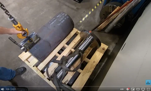
Same kind of idea as Edge Precision making this huge part:
1618766643387.webp
Simple and highly accurate approach - but that is a lot of material to turn into chips.

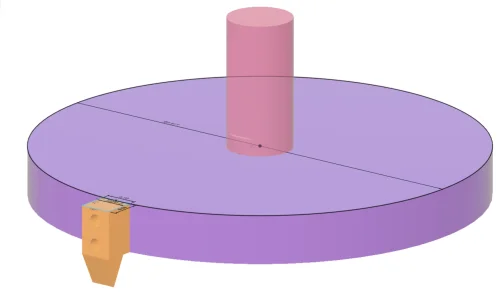
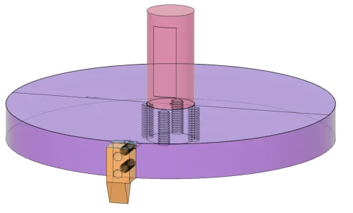
I was wondering about how else a disc could be attached to a shaft - tapers and key ways? Welding? Well no it would end up bent I'm sure. Well what about a press fit and drilled and threaded holes to replace a keyway? Is this a technique that could yield good results? Here is an example 1" hole with a 1.001" shaft - and interference press fit. Then holes drilled and threaded from the bottom 1/4-20 into the disc and shaft. Would the shaft end up 90 degrees to the disc? How big a press would one need to put the shaft into the disc? Would the screws even be necessary?
1618766031169.webp 1618765994765.webp 1618766173847.webp 1618766242917.webp
 
Last edited:
I think drilled keys like you have would be more than adequate. I would just leave the face & OD finishing to be turned in-situ so its perfectly balanced. (well.. except for the imbalance of the cutter but you have a big flywheel there).

You might be able to simplify the cutter by drilling a round hole matched to the circular shaft of a boring bar & then pins or set screws (since they have a flat) going in laterally like you have. Then you have all kinds of inserts & geometry options to choose from, easy to replace. I have butchered a few 10$ Ali boring bars for boring heads & other purposes & they work perfectly fine as long as you are using the cutting insert geometry correctly. I suspect the shanks are something like 4140. Don't do this on a high quality N-Am tool because the shanks could be much tougher material.

1618769168137.webp
 
For the design you have drawn above, you have to compensate for the large forces that will apply to your joint. Think as your spindle as being effectively an immovable object... All of the cutting force( For example 100kg) will be trying to turn the joint into a hinge.

For the design as outlined, I'd suggest sweating the joint together. A superior design would use a second plate, say 3/4 of an inch thick to enhance the strength of the joint and stiffen the interface. Of course use the largest diameter you can for the central pin. Registration is completely unimportant as long as the joint is completely solid. balancing happens after the fact.
 
I saw this video of a fly cutter build (did somebody post that here somewhere? thanks if you did) 3M views unbelievably. Interesting approach. In that video though his mill has 4 bolt holes parallel and part of the spindle that he can bolt the big disc too. I'm not sure what that kind of spindle is called. Here is the video


I was thinking about how to make one of these but something which would work with my equipment - an obvious but quite wasteful approach is to take a thick disc of material - say 3" thick and turn down a big portion of it to a small shaft that I could grab in a side lock tool older. e.g. quite similar to my face mill adapter I made recently: https://canadianhobbymetalworkers.com/threads/face-mill-adapter.3224/post-41804

Same kind of idea as Edge Precision making this huge part:
View attachment 14275
Simple and highly accurate approach - but that is a lot of material to turn into chips.

I was wondering about how else a disc could be attached to a shaft - tapers and key ways? Welding? Well no it would end up bent I'm sure. Well what about a press fit and drilled and threaded holes to replace a keyway? Is this a technique that could yield good results? Here is an example 1" hole with a 1.001" shaft - and interference press fit. Then holes drilled and threaded from the bottom 1/4-20 into the disc and shaft. Would the shaft end up 90 degrees to the disc? How big a press would one need to put the shaft into the disc? Would the screws even be necessary?
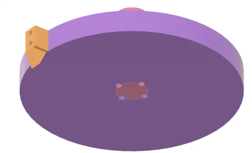
View attachment 14272 View attachment 14271 View attachment 14273 View attachment 14274
If you heat your fly cutter body in the oven and put the shaft in the freezer, it will fall in so no interference press work. You could put set screws in on the seam to key lock the two pieces together or v groove and put a small weld around the perimeter. You can only weld if no 4140 is used as a preheat may make the shaft loose in the hole while welding. If any thing is bent or twisted during assembly, you can always remachine it in the mill using the mill like a lathe and a cutting tool held in the vice.
 
You could machine a shallow taper and a shoulder onto the shaft end. Have a matching socket in the disc. Use a draw bolt to pull the shaft into the taper up to the shoulder. The shoulder increases the stiffness of the assembly.

In the video, he cuts a lathe tool holder in half (or about in half). He mounts the cut-off end on the opposite side for balance. You could always weigh the two pieces and match them by drilling lightening dimples in the heavy part.

I think fly cutters are not meant as “hogging” tools. They are generally used for finishing.
 
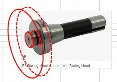
Yes, I imagined relatively light forces for fly cutting too, but it would be interesting to know exactly how much. Larger radius and/or bigger depth of cut would for sure put more load on any kind of retention system. Maybe another option is just thread a hole in a plate & use typical R8 arbor for boring head, typically 7/8-20 tpi threads but maybe they come bigger. I think this style of arbor its relying on a good mating surface of the underside. And thread retention means the rotation direction is limited to tighten mode as opposed to bad things will happen mode LoL.

I really wonder how much the disc mass would be adding to the finish vs a solid bar of something stiff like 4140. Most of the little flycutters are made from solid round because they are usually holding a square toolbit with multiple set screws.

1618783829743.webp
 
He would always have the cutter orientated in one direction anyways so the fly cutter would always have to spin in that direction (tightening against the threads). The only oops moment would be if you happen to have the switch in reverse & began cutting. Maybe not as bad as 'flywheel power' but not a good thing anyways. Best to have it pinned.

skip to 6:00 for the exciting bit...

or for something more relaxing...
 
Instead of that adapter... Use a boring head adapter. There's a fine thread on the circumference and a prethreaded hole in the bottom. O use a 1" shell mill adapter. Same deal.

A problem with these approaches with anything that is larger size. The strain at the connection is order X cubed. For short distances, such as a few inches, this won't matter. When the distances increase the forces escalate and the strain on the connection leads to the connection misbehaving. It depends on the quality of the steel and the rigidity of the connection, but these are linear factors, so the increase overwhelms the strength of the bolts holding it together.

If you need large distances, the Suburban Tool 'superfly' cutter is very well engineered, and can be made in the home shop if you don't like the $$$ price tag. Here's a link to the product. I have seen the finish it gives on a 16" wide fly cut, and it is very impressive. The design leads to making the forces go into shearing the milled in keyway - a practical way to reduce the problems at the joint.

https://www.subtool.com/st/fcs_fly_cutter_sets.html
 
The pic I showed is a boring head adapter. I mean thread the plate so its essentially same tightening principle as a boring head. Once tightened & surfaces are flush I would think that's pretty solid, no? One would have to shear the threads. But I agree a key/tab system is going to be more solid.
 

Attachments

  • SNAG-4-18-2021 0001.webp
    SNAG-4-18-2021 0001.webp
    13 KB · Views: 5
I saw this video of a fly cutter build (did somebody post that here somewhere? thanks if you did) 3M views unbelievably. Interesting approach. In that video though his mill has 4 bolt holes parallel and part of the spindle that he can bolt the big disc too. I'm not sure what that kind of spindle is called. Here is the video

K&T mills have 4 bolts on the spindle - horizontal mills, so that you can attach a gear to them. Also some very large face mills (8" plus) have 4 large bolts to attach to something - i.e. they do not take simple face mill adapters for 40 taper. 6" is the largest I seen for 40 taper that takes standard adapter.
 
John, do you have a boring head for your mill? there's a trick you can try if you do. Take a lathe boring bar and use it in your boring head. It is only good for very light cuts, but it works. You can easily span 6" that way.
 
John, do you have a boring head for your mill? there's a trick you can try if you do. Take a lathe boring bar and use it in your boring head. It is only good for very light cuts, but it works. You can easily span 6" that way.

ok, you have to explain that one to me:confused:
 
ok, you have to explain that one to me:confused:


Boring heads have vertical holes for boring bars, but also one horizontal hole. the boring bar can be put in the horizontal hole and be used to bore large holes, to to do light surfacing work. I hope this helps.
 
Yes you can use a large boring head for a very light passes - note that extended boring bar will not exactly be rigid in this application.
 
Back
Top