My lathe is a Busy Bee/Craftex CX701. I'm trying to figure out my nominal spindle dimensions: nose, bolt pattern.
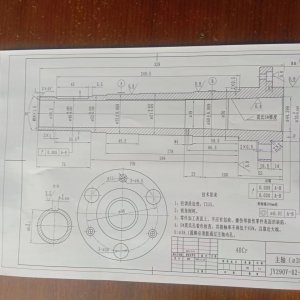
The spindle flange is 125mm. The nose is 70mm (2 3/4")across, with a 43.5mm (1.7") passthrough.
I've measured across the studs on a chuck, subtracted the diameter of one stud to get 84.4mm, and divided by sqrt(3) to get a nominal radius of 49mm (+- 0.5 on a lack of measurement repeatability), giving a bolt hole radius of 98mm, or 3.86", effectively.
I've been looking at tables of spindles, including, for instance, that at https://www.northlandtool.com/spindle-nose-standards/ .
Since there are no bolt holes in the nose itself, I expect it to be a B2 class spindle nose, but there is *nothing* I can see with anywhere near that bolt-hole radius.
Any idea where else to look up my nominal specifications? The manual is, of course, no help.
I'd love to know my nominal nose taper, for example, before machining a back plate to fit it. The landing is so short (7.14mm) that it's difficult to get a confident angle off it even with a DTI in the compound.
")