• Scam Alert. Members are reminded to NOT send money to buy anything. Don't buy things remote and have it shipped - go get it yourself, pay in person, and take your equipment with you. Scammers have burned people on this forum. Urgency, secrecy, excuses, selling for friend, newish members, FUD, are RED FLAGS. A video conference call is not adequate assurance. Face to face interactions are required. Please report suspicions to the forum admins. Stay Safe - anyone can get scammed.

Arduino questions

ShawnR

Ultra Member
Premium Member
I know some users here are familiar with the Arduino. It is kind of new to me, although I am familiar with other microcontrollers. I have tried searching for this answer but cannot seem to find the key words. I am sure someone here knows the answer.

Relating to my old days of programming, remember the Gosub routine? or "If then go to ". What is the eqivalent in Arduino speak?

example, mill power feed....in the loop we read the speed control and adjust the pulse rate, the motor reacts and we go back and do it again. But if I want to install a limit switch, and have the state checked within the loop, that is no problem, but how do I get out of the loop? ie table hits end of travel....stop motor and light indicator? In the old days.....it would have been "If switch= 1 then goto "shutdown" but I cannot translate to arduino.

Anyone?
 

deleted_user

Super User
Shawn,

You may also find this reference guide helpful.

Arduino programming language can be divided in three main parts: functions, values (variables and constants), and structure.


ShawnR

Ultra Member
Premium Member
For you guys that have built their Arduino projects permanent, how did you make it permanent? Did you buy the 328 chip and make a breadboard or just use the connections on the protoboard and mount it into an enclosure? I am using the Arduino UNO and starting to think about putting it into a box. Anyone have any photos of the final installation?
 

YYCHM

(Craig)
Premium Member

I just get that thing that exposes the UNO pins to screw down locations (can't think of what they are called right now) and stick that in a box with double sided tape. That and a 9V battery holder. LCDs get epoxied in 4 corners.

Nothing has come loose so far:p

I just remembered.... It's called a shield.
 
Last edited:

ShawnR

Ultra Member
Premium Member

I just get that thing that exposes the UNO pins to screw down locations (can't think of what they are called right now) and stick that in a box with double sided tape. That and a 9V battery holder. LCDs get epoxied in 4 corners.

Nothing has come loose so far:p

I just remembered.... It's called a shield.

Thanks Craig. I have not looked at that thread. I think I was in the midst of building a brick oven last fall when it was most active and if I did glance at, I was not into the Arduino much at the time. There is a lot of great Arduino in the thread! Thanks everyone for posting and also, Wow! the projects are very impressive! I thought I was doing well yesterday, finally feeling a little more comfortable with the Arduino syntax and recalling MCU programming from years ago, but this thread humbled me.

My Arduino project is the installation of a stepper motor on my mill for the X-axis power feed. I am wanting to display feed speed on the 16x2 display as well. I am trying to do it in a way for future options, not that I would ever do CNC, but good practice to not lock into only current needs. My code was/is clunky. I am displaying the data in the motor loop and have found that the time it takes to write to the LCD affects the motor speed, virtually eliminating the need for delays, but then, removing speed control flexibility. I have it working at least, so now to clean it up and make it more efficient. I am not using the LCD interface as I have enough pins available on the Arduino, but I am wondering if using the interface will take some duties from the processor, thus speeding it up. Does anyone know? I do have the interfaces already. I found a library that uses a 2 wire interface that Parallax used to sell for MCU's, which I have, but I have not tried that one yet. It seemed to take me a while to get my head around the Arduino IDE but it is coming along.

I have a terminal shield too so will probably use that for the permanent mounting. I was wondering if anyone was getting the chip itself, and installing it into a PC Board

https://www.robotshop.com/ca/en/atmega328-arduino-bootloader.html

and there are others. But realistically, and after looking at the options, I think the Nano is the better choice. If I had one, I would use it. The PC board work is done for you with oscillators and support circuitry. I only have the UNO boards but I have a few so will just install one of them. My track record is that I spend hours and days prototyping something, get it working, then drop the ball and it does not make it to installation. I think that subconsciously, I just want to see if I can do something, but in the end, realize that it was not necessary....:rolleyes: But this one has to get installed! New goals in retirement....haha

Here is the x-axis power feed prototype and the terminal shields. I must have ordered them on speculation a while back. They will be fine for this application.
 

Attachments

  • 20220403_101553.jpg
    20220403_101553.jpg
    430.7 KB · Views: 7
  • 20220403_102347.jpg
    20220403_102347.jpg
    478.6 KB · Views: 7

ShawnR

Ultra Member
Premium Member
Gee Shawn, you're like a third of the way to a CNC!
@David_R8 lol...yea. I was thinking that too! That is why I am going with the controls the way I am. Everything goes through the controller, like Jog, Limit switches, direction, etc. Then I can alter them in the programming as needed, maybe, someday, versus hardwiring everything. A simple DC motor would have been much easier, but then I would have had no excuse to learn a bit about the arduino. When I had the mill apart for the DRO install, I noted that a stepper on top of the Z-axis leadscrew would install very easily too. The y would actually be the most difficult, due to position and space. Lots of guys have converted this mill so it is certainly doable.
 

van123d

Well-Known Member
Shawn,
Maybe this has been mentioned in the attached thread but you might want to look into using interrupts for your code. Especially for things like your limit switches.
 

ShawnR

Ultra Member
Premium Member
Shawn,
Maybe this has been mentioned in the attached thread but you might want to look into using interrupts for your code. Especially for things like your limit switches.
Thanks @van123d . That was my initial thought too, at least for the limit switches. But then, while writing the code, I realized that the processor is so fast and the loop gets done so quickly that the time difference in hitting a table limit being detected by an interrupt or picked up in the loop will not be much difference, for this application. (I don't think...?)

And I don't know much about using the interrupts, yet..... so this was easier. If you thinking of interrupts for other facets of the program, yea, not there yet.

Here is the code if anyone is interested. Be gentle, this is my first Arduino project....;) I am open to input but hoping to not do a whole rewrite. I am trying to learn how to get RPM out of the MCU. The guys on the Arduino forum are working with me. Another learning curve I scale.....:rolleyes:


#include <LiquidCrystal.h>
#include <Stepper.h> //don't think this is needed for this application but it did appear to smooth the motor operation for some reason.

/*
LCD RS pin to digital pin 12
LCD Enable pin to digital pin 11
LCD D4 pin to digital pin 4
LCD D5 pin to digital pin 5
LCD D6 pin to digital pin 6
LCD D7 pin to digital pin 7
LCD R/W pin to ground
10K resistor:
ends to +5V and ground
wiper to LCD VO pin (pin 3 on display!)
v 6600 motor controller set to 800
*/

int dirpinout = 3; //direction pin out to controller
const int dir_in = A2; //direction control pin in from switch
int dir = 1; // sets table direction initially CW is table left
int enablepin = 9; //enable pin out to controller
int enableout = 1; //sets motor off to start
int pulse = 2; // pulse out pin to controller
const int potin = A0; //speed pot connected to pin A0
int speedpulse = 500; // pulse delay for speed management
int runpin = A1; //run button enables or disables motor
int runn = 0; //sets runn to state of runpin (low to run)
int jogin = A3; //jog switch in
int jogout = 0; //jog out
const int limitpin = A4; //limit switch input
const int limitled = 13; // limit indicator connected to pin A5** may not be connected
int limit = 0; //limit switch state

// initialize the library by associating any needed LCD interface pin
// with the arduino pin number it is connected to
const int rs = 12, en = 11, d4 = 4, d5 = 5, d6 = 6, d7 = 7;

LiquidCrystal lcd(rs, en, d4, d5, d6, d7);

void setup() {

//Serial.begin(9600); // open the serial port at 9600 bps:
pinMode(limitpin, INPUT_PULLUP);
pinMode (dir_in, INPUT); // switch takes pin low, otherwise, pin is high due to pullup
pinMode (limitled, OUTPUT);
pinMode (enablepin, OUTPUT); //high to enable
pinMode (pulse, OUTPUT);
pinMode(dirpinout, OUTPUT); //high for clockwise ****check this
pinMode(runpin, INPUT); //Run button enables motor to run
pinMode(jogin, INPUT); //Jog button in
// set up the LCD's number of columns and rows:
lcd.begin(16, 2);
}

void loop() {
limit = digitalRead(limitpin); //one to run, zero if at limit
digitalWrite(limitled, limit); //lights indicator
runn = digitalRead(runpin); //zero to run, one to not run
jogout = digitalRead(jogin);
dir = digitalRead(dir_in); //sets motor direction according to switch
digitalWrite(dirpinout,dir);

lcd.print("Speed___");
lcd.print(15000-speedpulse);
lcd.clear();

if (limit + runn == 2) // if run on and limit not reached, enable controller
{
digitalWrite(enablepin, LOW);
}
else if (limit + jogout == 2)
{
digitalWrite(enablepin, LOW); //if jog on and limit not reached, enable controller
}
else {
digitalWrite(enablepin, HIGH); //disable controller
}


speedpulse = analogRead (potin); //reads speed pot
speedpulse = map (speedpulse, 0, 1023, 0, 15000); //converts pot to speed delays
digitalWrite (pulse, HIGH); //pulses motor
delayMicroseconds(speedpulse); //delay
digitalWrite (pulse, LOW); //pulses motor off
delayMicroseconds(speedpulse); //delay

//Notes count pulse. 400 pulses = 1 revolution
//count time elapsed since start of counting and convert to seconds for rpm calculation
//calculate feed speed at 0.100"/revolution
}
 

van123d

Well-Known Member
This can work, but maybe not the ideal method. Two things that stick out to me that might not be a problem right now as your program is small and simple, but could become an issue later as it grows. As I mentioned, not using interrupts you are waiting for your program to decide to check if a limit switch has been hit. As you say, right now it is running through the loop fast enough that it does not seem to be an issue but if it grows, or serial communication hangs, etc you could be in a situation where it has not stopped when it should have. This may not be an issue and may never be an issue but I would want my limit switches to be something that is dealt with immediately, not when the program gets around to it. Input buttons are similarly better handled with interrupts but not as critical if you miss an input.

The second thing is to simplify your motor timing. Right now, assuming you have equal delay for motor on and motor off, you would have unequal pulse on/off time. as your pulse off time includes all of the other code to poll your inputs, write the serial communication etc. This could make it difficult to accurately calculate and set speeds.

If you had the motor control as a separate function that simply did the pulse on/off then it simplifies the motor control and makes it easier to calculate and adjust timing. Basically your program would stay in the motor control function unless something, control button, or limit switch, interrupts it. It would then check what interrupt triggered it, act on that input accordingly, update your display, then resume the motor function (unless limit switch or stopped).

Not sure if that makes sense, your code can work the way you have it today, but learning and structuring your code to use functions and interrupts will make it easier on you later if you want to add features or make changes.
 

ShawnR

Ultra Member
Premium Member
OK, Thank you @van123d . I am not too sure (ie I know they exist) but I do not know how to use functions. I come from the old world of gosub or goto, etc. But I understand and agree with your comments, just not sure how to implement them yet.
 

Janger

(John)
Administrator
Vendor
Looking like great progress Shawn. I enjoyed reading through your loop function. For the hardware how do you plan to make your circuits permanent?
 

ShawnR

Ultra Member
Premium Member
Looking like great progress Shawn. I enjoyed reading through your loop function. For the hardware how do you plan to make your circuits permanent?
Great question @Janger . I am struggling with that. The Arduino is not built to be permanent but it does have 4 screw holes. A younger Shawn would have etched the pc board for the at328 and installed terminal strips but the new Shawn, (a little lazier, less nerdy, and good friends with Amazon) is pursuing other options. I found a kit on line with standoffs, etc., Then the other connections will be either the break out board in Post 7, although I will need to support it somehow with some spacers, or just ribbon cables to terminals. The breakout board (aka shield) does not have much area for screw mounting but if the cables are secured and the Arduino board is mounted, there should not be much stress on the breakout boards.

The rest of it will be in 3 modules. The control panel will hold the display and controls only. The . power supply will go into a box with the motor controller, mounted behind or below the mill, out of the way, and the stepper motor just has 4 wires to it. That was part of the appeal of the stepper motor install was that it is fairly compact for its power, compared to a similarily sized DC motor, from what I could see. And if this one does not have enough torque, there are larger NEMA 23 motors that have more than enough so my motor mount won't change. I ordered a couple of small couplers from Amazon, similar to lovejoy couplings. Should I not "nail" my alignment motor to table adapter, hoping the coupling will accommodate.

So that is the plan. It has been a few days back on the electronics bench but the project is coming together. I should be starting the motor mount today or tomorrow.

The program code is changing often, since posting it. @van123d has inspired me to pursue better ways of doing it. As I learn more about the Arduino, I am trying to update. At some point between going to bed and getting up, I came up with the idea that it would be cool to be able to punch in or dial in an x location and have the stepper go to it.....:rolleyes: This could become another ongoing saga!

And this all started because I got tired of turning the handwheel on the odd project I do on the mill.....;) and all you guys were boasting (oops, posting) about your power feeds.....haha

All good,
 

ShawnR

Ultra Member
Premium Member
Here is the schematic. It might not totally coincide with the code posted above because both are changing. One obstacle I had was to ensure that if the run switch or jog switch was activated, it did not overwrite a limit violation, ie, going the wrong way once a limit was violated. The motor is so small, it would not damage it, but maybe a piece resting against a cutter. So I had various options but I think (know) that implementing an interrupt, mentioned earlier, would be the better way to go.

Same as usual, just bumbling along, see what happens.
 

Attachments

  • Power feed schematic.bmp
    866.3 KB · Views: 11
Last edited:

whydontu

I Tried, It Broke
Premium Member
Very minor suggestion. Stick a 220 ohm resistor between +5v and any of your input switches/pots. Wont affect operation, but might save your Arduino and power supply if something shorts to ground. You can use the <map(analogRead(MyPin)> function to scale up to compensate for the slight loss of pot range.
 

ShawnR

Ultra Member
Premium Member
Very minor suggestion. Stick a 220 ohm resistor between +5v and any of your input switches/pots. Wont affect operation, but might save your Arduino and power supply if something shorts to ground. You can use the <map(analogRead(MyPin)> function to scale up to compensate for the slight loss of pot range.
Thanks. Good point. I am mapping the pin already on the pot input and I don't think that will affect the digital inputs. But will watch for it.
 

ShawnR

Ultra Member
Premium Member
This can work, but maybe not the ideal method. Two things that stick out to me that might not be a problem right now as your program is small and simple, but could become an issue later as it grows. As I mentioned, not using interrupts you are waiting for your program to decide to ..........

Not sure if that makes sense, your code can work the way you have it today, but learning and structuring your code to use functions and interrupts will make it easier on you later if you want to add features or make changes.

I had it working with the previous program, then took your advice and incorporated an interrupt for the limit switch, and only write to the LCD once per loop . I also took the display and stop functions out of the main loop. Good learning along the way, lots of time invested but lots of that learning time, but all good. Need more projects for the Arduino now.

Thanks for the input.

Below is the latest code if anyone is interested

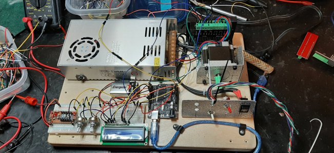
/*This program is intended for an Arduino UNO to run a power feed on a milling machine x axis. It drives a TB6600 Stepper motor controller
* running a NEMA23 stepper motor. It display feed rate, based on 0.100"/revolution of the lead screw.
* It accomodates a limit switch and displays the status of a limit violation.
* April 12 2022
* Enable signal to motor controller is LOW to enable motor
* variable "stopp" = 0 to enable motor
*
*/

#include <LiquidCrystal.h>

/*
LCD RS pin to digital pin 12
LCD Enable pin to digital pin 11
LCD D4 pin to digital pin 4
LCD D5 pin to digital pin 5
LCD D6 pin to digital pin 6
LCD D7 pin to digital pin 7
LCD R/W pin to ground
10K resistor:
ends to +5V and ground
wiper to LCD VO pin (pin 3 on display!)
6600 motor controller set to 400
*/

const int dirpinout = A5; //direction pin out to controller
const int dir_in = A2; //direction control pin in from switch
int dir; // sets table direction initially CW is table left
const int enablepin = 8; //enable pin out to controller
int enableout; //sets motor off to start
const int pulse = A4; // pulse out pin to controller
const int potin = A0; //speed pot connected to pin A0
int speedpulse; // pulse delay for speed management
const int runpin = A1; //run button enables or disables motor
int runn; //runn state(low to run)
const int jogin = A3; //jog switch in
int jogout; //jog out
const int limitpin = 2; //limit switch input
const int limitled = 13; // limit indicator connected to pin 13** may not be connected
int limit; //limit switch state
unsigned long tsrpm = 0; //tsrpm is start of timer for rpm
unsigned long tfrpm = 0; //tfrpm is stoptime for rpm count
int loops = 0; //loops is counter for loop cycles to use for rpm
int rpm = 0; //rpm
const int setpulse = 1600; //set to pulse setting on controller
volatile int stopped = 1; //stop is used to stop motor till a manual reset by activating jog

// initialize the library by associating any needed LCD interface pin
// with the arduino pin number it is connected to

const int rs = 12, en = 11, d4 = 4, d5 = 5, d6 = 6, d7 = 7;
LiquidCrystal lcd(rs, en, d4, d5, d6, d7);

void limitisr () {
stopped = 1; //stopped flag 1 should stop motor
//Serial.println("isr"); //used to troubleshoot
}

void setup() {

Serial.begin(9600); // send and receive at 9600 baud

pinMode(limitpin, INPUT_PULLUP); //limitswitch low when violated
pinMode (dir_in, INPUT_PULLUP); // switch takes pin low, otherwise, pin is high due to pullup, setting direction
pinMode(runpin, INPUT_PULLUP); //Run button enables motor to run
pinMode(jogin, INPUT_PULLUP); //Jog button in

pinMode (limitled, LED_BUILTIN); //just an indicator
pinMode (enablepin, OUTPUT); //high to controller to enable
pinMode (pulse, OUTPUT); //pulse to controller
pinMode(dirpinout, OUTPUT); //dir to controller for clockwise ****check this

lcd.begin(16, 2); // set up the LCD's number of columns and rows:
loops = 0; //sets completed loops to 0

attachInterrupt(digitalPinToInterrupt(limitpin), limitisr, LOW);

}

void loop() { //main loop

limit = digitalRead(limitpin);
runn = digitalRead(runpin); //zero to run, one to not run
jogout = digitalRead(jogin); //jogs motor if jog button pushed

//reset after limit violation
if ((limit == 1) && (jogout == LOW)) { //if limit ok and jog button pushed, reset stopp flag
stopped = 0;
}

if (stopped == 1) { //stopp == 1 disables motor
stopp(); //go to stopp function

}
else {
++loops; //increments counter for loops
}
if (loops == 1) { //gets time of first loop since a reset
tsrpm = millis(); //sets the time of the start tsrpm
}
else if (loops == setpulse) { //checks to see if the number of loops equals the number of steps on controller
tfrpm = millis(); //gets final time for rpm calculation
loops = 0; //resets loops counter
displaydata(); //goes to display data function
}

dir = digitalRead(dir_in); //reads motor direction according to switch
digitalWrite(dirpinout, dir); //sets dir pin to controller

if ((stopped == 0) && (runn == 0)) { // if run on and limit not reached, enable controller
digitalWrite(enablepin, LOW); //enables motor
}
else if ((stopped == 0) && (digitalRead(jogin) == 0)) { //if jog on and limit not reached, enable controller
digitalWrite(enablepin, LOW); //enbables motor
}
else {
digitalWrite(enablepin, HIGH); //disable controller see if this allows manual movement of table
}

speedpulse = analogRead (potin); //reads speed pot
speedpulse = map (speedpulse, 0, 1023, 10, 16000); //converts pot to speed delays max is 16383

digitalWrite (pulse, HIGH); //pulses motor
delayMicroseconds(100); //100 usec pulse delay
digitalWrite (pulse, LOW); //pulses motor off
delayMicroseconds(speedpulse); //delay
}

void displaydata() { //function to display data is called once per loop

rpm = 60000 / (tfrpm - tsrpm); //converting numbers to minute values
lcd.clear();
lcd.print("RPM Feed in/min");
lcd.setCursor(0, 1);
lcd.print(rpm);
lcd.print(" --- ");
lcd.print(rpm * 0.1);
}

void stopp() { //stopp function for limit violation
lcd.clear();
lcd.print("Clear limit then");
lcd.setCursor(0, 1);
lcd.print("Jog to reset");
delay (100);
}
 
Top