You are using an out of date browser. It may not display this or other websites correctly.
You should upgrade or use an alternative browser.
You should upgrade or use an alternative browser.
Tool Another DIY made shop tool
- Thread starter KeeponDragon
- Start date
Tool
KeeponDragon
Super User
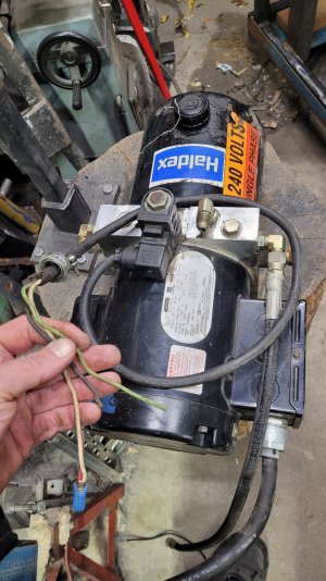
I hooked er' up to the shop air last night. The porta-power cylinder the original maker used, had a failed o-ring between the two bodies. Upon disassembly, I found a large, grooved seal that had basically come apart, looked like cookie crumbs.
I should have taken pics, but my hands were covered in AW32.
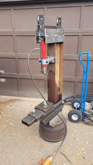
I've now done some minor modifications, to accommodate a cylinder I had in my hoard.
First was to knock this post off that held the porta power ram.

Diablo hole saws...love these things. At some point, I have to remember to make an adapter for em' to fit my pipe notcher.
Anyway, it took some time, and a bit of cutting fluid, but I got through the 20mm of material.
It's probably overkill, and will probly twist the I-beam better than the hips of belly dancer, but it's what I had.
The mounting lug on the barrel now comes through the top of the press, with a pin to hold it in place.
It's far from complete obviously, but I'm moving in a forward direction.
I have the power pack that accompanied the cylinder when I picked it up. From another hydraulics project, I have a control valve. So then it's just plumbing, and deciding where the power pack is going to reside.
At some point, I'm hoping to have a cart I can set up with the powerpack, and run it off the 220 in the shop.
Quick connects will be used. So I can move the power from one hydraulic tool to another....
A bit of inspiration from Colin Furze, that maniac maker in the UK...
I should have taken pics, but my hands were covered in AW32.
I've now done some minor modifications, to accommodate a cylinder I had in my hoard.
First was to knock this post off that held the porta power ram.

Diablo hole saws...love these things. At some point, I have to remember to make an adapter for em' to fit my pipe notcher.
Anyway, it took some time, and a bit of cutting fluid, but I got through the 20mm of material.

It's probably overkill, and will probly twist the I-beam better than the hips of belly dancer, but it's what I had.
The mounting lug on the barrel now comes through the top of the press, with a pin to hold it in place.

It's far from complete obviously, but I'm moving in a forward direction.
I have the power pack that accompanied the cylinder when I picked it up. From another hydraulics project, I have a control valve. So then it's just plumbing, and deciding where the power pack is going to reside.
At some point, I'm hoping to have a cart I can set up with the powerpack, and run it off the 220 in the shop.
Quick connects will be used. So I can move the power from one hydraulic tool to another....
A bit of inspiration from Colin Furze, that maniac maker in the UK...
KeeponDragon
Super User
So, does anyone have hydraulics experience?
I have the skills to assemble hoses. It was a job priority when I worked for Napa/Traction in Fort Mac.
Beyond that, I understand that there is pressure and flow.
My challenge is with the hyd. power unit I have for this project. It was originally spec'd for use with a "dock leveler". Basically, a flat deck, that articulated, to get the loading dock level with the truck/trailer at a warehouse.
It took a bit of digging, but I came up with the manufacturers manual for the leveler, which had the subset of instructions for the hyd. unit.
I had hoped to just use the manual valve I have on hand with it. But after looking at the drawing the valve body cross section, I don't think I can. There is still one solenoid attached. It's got 4 wires out of it. I am assuming (bad idea, I know) that they're for power to the solenoid, and for in and out on the shuttle portion of the solenoid.
If anyone has some insight or suggestions...I'm all ears.
thanks!

Tractors have a lot of hydraulics in them, so I guess I qualify to help provide useless advice......
If all you are doing is raising and lowering the ram, you can use the power pack to generate pressure and flow and a simple hand SCV to control it. Think Log Splitter.
I have no idea why there are 4 wires on the main solenoid. Do you also have a wiring diagram?
If all you are doing is raising and lowering the ram, you can use the power pack to generate pressure and flow and a simple hand SCV to control it. Think Log Splitter.
I have no idea why there are 4 wires on the main solenoid. Do you also have a wiring diagram?
Former Member
Guest
They are not wires but hydraulic lines. Same idea as an electrical diagram but with fluid.
Doggggboy
Ultra Member
They are not wires but hydraulic lines. Same idea as an electrical diagram but with fluid
The solenoid portion would be wiring, wouldn't it?
Like an electrically controlled valve for the hydraulic fluid?
KeeponDragon
Super User
And like I said, any advice or wisdom is appreciated, useless or notTractors have a lot of hydraulics in them, so I guess I qualify to help provide useless advice......
If all you are doing is raising and lowering the ram, you can use the power pack to generate pressure and flow and a simple hand SCV to control it. Think Log Splitter.
I have no idea why there are 4 wires on the main solenoid. Do you also have a wiring diagram?

That is basically all I need to do. But, I'm unsure of where to plumb off of to the hand valve. I think the 4 wire solenoid is for shuttling flow through the valve body.
I went back and found the manual....and it's in pdf...so it'll take me a bit to clip out the wiring section and post as an image.
I'm on a mac laptop...so everything gets convoluted for me...but I did get this to come up nice.
What I do not have attached, is the Lip solenoid valve SV4, and the lower manifold block.

KeeponDragon
Super User
I don't have any experience with hydraulic power pack and control valve and .........
But interested how things work.
Is there more than one control lever on your valve body? or one lever with multiple position and a center neutral position.
I wonder if you were to plug the lip circuit SV4 port and see what happen. I google hydraulic press circuit diagram images and there is a lot of examples of how the lines are hook up.
KeeponDragon
Super User
The pdf implies there was at least 2 solenoids. One for the leveling cylinder and one for the lip.I don't have any experience with hydraulic power pack and control valve and .........
But interested how things work.
Is there more than one control lever on your valve body? or one lever with multiple position and a center neutral position.
I wonder if you were to plug the lip circuit SV4 port and see what happen. I google hydraulic press circuit diagram images and there is a lot of examples of how the lines are hook up.
pretty sure it had push buttons when it was built.
As I don't have any of those, my hope was to run the pack just as a pressure supply. Instead of electronics, just manual valving.
As I don't have any of those, my hope was to run the pack just as a pressure supply. Instead of electronics, just manual valving.
I'll download the pdf and take a boo.
I think your plan is exactly what I would do. For your application you really only need a pump to supply oil under pressure and a manual valve to control where the oil goes.
I'll get back to you once I've had some toilet time to read the pdf.
historicalarms
Ultra Member
Hydraulics are just "flow control" of a pressure situation created by the pump. The system Pressure force can be regulated by pump volume/speed or by relief valve setting. Not using a relief valve can unknowingly create very dangerous pressures especially in gear driven pumps, gear train does not fail before other components reach their bursting limit, belt driven pumps, unless they have a humungus belt drive, usually squeal the belt. I have been told that those old belt driven power steering pumps on 70-80's vehicles can produce 12,000 psi if driven hard enough.
That solenoid will just divert oil from one passage to another of your choosing, it will not be a relief valve, the relief valve will be built into the other control spools of the control body (prob has one "dump" journal that directs oil back to the reservoir that is relief controlled.
You only need one "live" circuit so my opinion is that you dont need that solenoid hooked up, just identify the spool it is feeding and plumb into that line.
All the above is the simple stuff, now to compicate things you are going to have to hook the single acting ram ( at least I can only see one hose coming out of that ram) to what might be a double acting system ( a system that pressures both push & retraction of the ram). On a single acting system you need a "free flow" oil return to the reservoir. Trial & error to find what will work for you if that is a closed double acting system is all that I can come up with from a distance.
historicalarms
Ultra Member
I think 1/16 is way too much of a minimum movement with a hyd press, sometimes less than .005 is all I want for a press to move...I actually think 1/16" would be dangerous in some instances when in the higher force echelons.
Doggggboy
Ultra Member
I would guess that the 1/16" would be with no load.I think 1/16 is way too much of a minimum movement with a hyd press, sometimes less than .005 is all I want for a press to move...I actually think 1/16" would be dangerous in some instances when in the higher force echelons.
KeeponDragon, I take it you have the block assemblely that has the reservoir attached to it and still mounted to the motor/pump? As per post #10. The manifold block most likely not needed is below the motor. Is the Main solenoid valve"A"SV2 there? The Lip extend port and the Manifold Port A, the Main &Lip Cylinder Retract Tee port I believe are pressure ports. The Lip extend port and the Manifold Port A, appear to be switched by the Main solenoid valve "A"SV2. Flow can be returned into the return port, just below the sequence valve. The orange marker has covered some of the drawing, so not able to see all the passages.
This is some guess work on it, may help or not.
The ram (black unit) is a double acting, will need to decide if useing spring/cable weight return or going to pump back.
This is some guess work on it, may help or not.
The ram (black unit) is a double acting, will need to decide if useing spring/cable weight return or going to pump back.