I can't find the interesting thread on the 3d print process - I know it's here but where did it go?
I will move this to that thread when somebody tells me where???
This is my take on the CAD through to plastic printed result.
Here is a letter G house number with standoffs. Designed in CAD the 3D printer (at least not the kind I can afford) can't use that file to print a part directly. It needs to be converted in a two step process.
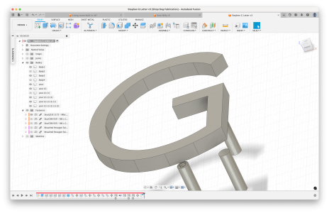
The first step is to convert the CAD model into a file format, (.STL or .3dMF) which a 3d printer utility software package can import. That software is nicknamed 'a slicer' and includes BambuStudio, Prusa Slicer, Cura, and there are others. The slicer software creates the instructions the 3d printer can follow by parsing the 3d model file.
The 3d model file, .STL file, is a representation of your CAD designed part but converted entirely into triangles. It is a raster type file from your vector cad model. It looks like this when created, viewed, in Fusion 360.
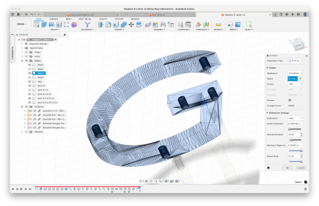
See all the triangles? You can see there are various output adjustments for resolution and such. The format does not support curves directly, curves have a stair step appearance which can be minimized by increasing the resolution (making a lot of small triangles) which of course makes the file bigger, requires more resources etc. no surprise.
The second major step is to load the .STL of your model into the 3d printer slicer software and it will "Slice" your model into individual layers according to a lot of parameters you have control over. Those layers, which are made up of lines of filament, are then converted into physical movement commands the 3d printer can actually execute. One layer at a time, one movement at a time, it's still magical I think. These instructions are GCODE similar to the gcode your CAM software produces to run on a CNC machine.
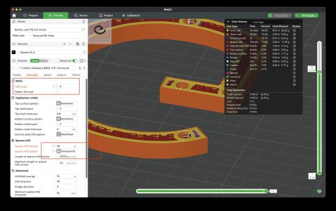
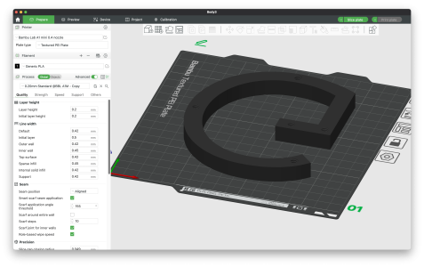
Here is the G loaded into the slicer. See all the parameters, 5 tabs of parameters. How many layers of plastic do you want on the sides, top and bottom of the part? 2 on the sides is default but you might want more for strength. How dense should the inside be? Solid like wood? Or less like cardboard? 15% grid is typical but you might want more and maybe a lot more. The more you add of course the stronger the print and the slower it prints.
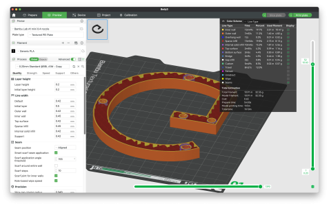
Here you can see the inside of the part sliced with 2 perimeters and 15% infill.
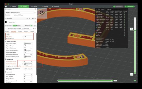
Here I have adjusted the parameters to have more perimeter layers putting a lot more meat around the screw holes as well as the part edges. And I changed the infill pattern from grid to honeycomb. Finally I changed the nozzle from 0.4mm (standard size) to a 0.8mm nozzle. The 0.8mm nozzle puts down a lot more material in the same time period, big fat lines of filament, at a cost of reduced resolution and quality. This means the print time only increased by 20 minutes instead of doubling despite printing more perimeters and such.
After making your choices on parameters then you can slice the model, generate the GCODE file, and export the file to a USB drive, or save it on the network, or more typically have the slicer just send it to the printer and tell it to go. Some people have a lot of privacy concerns about that file going to a cloud service for staging before it hits your printer. I'm not too concerned. If it was my clients intellectual property I might be a lot more concerned. You can walk your file to your printer on the usb drive if you deem that necessary. On the prusa you can spool to the printer without going through cloud if you want - then it is just going across your local network. Does Bambu support that? I'm not sure.
Here is a snippet of a gcode file from another print. This time is was for a replacement fan shroud on my printer which I wrecked.: fan-shroud-R2_0.2mm_PETG_MK3S_47m.gcode - I attached this file as a zip if you want to go look through the whole thing.
You can see all these G1 X Y E statements. This is actual printer command - G1 means move the print head to this x y location and extrude at the rate specified. The slicer lays down filament at different rates for different features, nozzle sizes, material, location etc. etc. and yes you can fiddle with all that if you want. The feed rate (or speed the head moves at) is the G1 F3000 command. I'm not sure about the units - mm/min?
The G3 is a command to move in an arc from where the print head is to an XY location moving around a point specified by I and J.
There you go - A - Z for most things I do. There are other ways too, downloading models, using the primitive tools in the slicer to make shapes, tinker cad or ...?
I will move this to that thread when somebody tells me where???
This is my take on the CAD through to plastic printed result.
Here is a letter G house number with standoffs. Designed in CAD the 3D printer (at least not the kind I can afford) can't use that file to print a part directly. It needs to be converted in a two step process.

The first step is to convert the CAD model into a file format, (.STL or .3dMF) which a 3d printer utility software package can import. That software is nicknamed 'a slicer' and includes BambuStudio, Prusa Slicer, Cura, and there are others. The slicer software creates the instructions the 3d printer can follow by parsing the 3d model file.
The 3d model file, .STL file, is a representation of your CAD designed part but converted entirely into triangles. It is a raster type file from your vector cad model. It looks like this when created, viewed, in Fusion 360.

See all the triangles? You can see there are various output adjustments for resolution and such. The format does not support curves directly, curves have a stair step appearance which can be minimized by increasing the resolution (making a lot of small triangles) which of course makes the file bigger, requires more resources etc. no surprise.
The second major step is to load the .STL of your model into the 3d printer slicer software and it will "Slice" your model into individual layers according to a lot of parameters you have control over. Those layers, which are made up of lines of filament, are then converted into physical movement commands the 3d printer can actually execute. One layer at a time, one movement at a time, it's still magical I think. These instructions are GCODE similar to the gcode your CAM software produces to run on a CNC machine.
Here is the G loaded into the slicer. See all the parameters, 5 tabs of parameters. How many layers of plastic do you want on the sides, top and bottom of the part? 2 on the sides is default but you might want more for strength. How dense should the inside be? Solid like wood? Or less like cardboard? 15% grid is typical but you might want more and maybe a lot more. The more you add of course the stronger the print and the slower it prints.

Here you can see the inside of the part sliced with 2 perimeters and 15% infill.

Here I have adjusted the parameters to have more perimeter layers putting a lot more meat around the screw holes as well as the part edges. And I changed the infill pattern from grid to honeycomb. Finally I changed the nozzle from 0.4mm (standard size) to a 0.8mm nozzle. The 0.8mm nozzle puts down a lot more material in the same time period, big fat lines of filament, at a cost of reduced resolution and quality. This means the print time only increased by 20 minutes instead of doubling despite printing more perimeters and such.

After making your choices on parameters then you can slice the model, generate the GCODE file, and export the file to a USB drive, or save it on the network, or more typically have the slicer just send it to the printer and tell it to go. Some people have a lot of privacy concerns about that file going to a cloud service for staging before it hits your printer. I'm not too concerned. If it was my clients intellectual property I might be a lot more concerned. You can walk your file to your printer on the usb drive if you deem that necessary. On the prusa you can spool to the printer without going through cloud if you want - then it is just going across your local network. Does Bambu support that? I'm not sure.
Here is a snippet of a gcode file from another print. This time is was for a replacement fan shroud on my printer which I wrecked.: fan-shroud-R2_0.2mm_PETG_MK3S_47m.gcode - I attached this file as a zip if you want to go look through the whole thing.
; FEATURE: Inner wall; LINE_WIDTH: 0.5G1 F3000G1 X104.609 Y92.701 E1.12912G1 X104.609 Y82.276 E.38829G1 X146.425 Y82.276 E1.55749G1 X146.425 Y143.388 E2.2762G3 X139.695 Y146.861 I-105.693 J-196.554 E.28208You can see all these G1 X Y E statements. This is actual printer command - G1 means move the print head to this x y location and extrude at the rate specified. The slicer lays down filament at different rates for different features, nozzle sizes, material, location etc. etc. and yes you can fiddle with all that if you want. The feed rate (or speed the head moves at) is the G1 F3000 command. I'm not sure about the units - mm/min?
The G3 is a command to move in an arc from where the print head is to an XY location moving around a point specified by I and J.
There you go - A - Z for most things I do. There are other ways too, downloading models, using the primitive tools in the slicer to make shapes, tinker cad or ...?
Attachments
Last edited:

