• Spring 2024 meetup in Calgary - date Saturday, April 20/2024. discussion Please RSVP Here to confirm and get your invitation and the location details. RSVP NOW so organizers can plan to get sufficient food etc. One week to go! More info and agenda
  • We are having email/registration problems again. Diagnosis is underway. New users sorry if you are having trouble getting registered. We are exploring different options to get registered. Contact the forum via another member or on facebook if you're stuck. Update -> we think it is fixed. Let us know if not.
  • Spring meet up in Ontario, April 6/2024. NEW LOCATION See Post #31 Discussion AND THE NEW LOCATION

Machine 12" Box Pan Brake

Machine

jcdammeyer

John
Premium Member
Well drat. This whole thread went missing. Not about to repeat myself all over again. Instead I'll just say that the Princess Auto on sale 12" box pan brake has some design issues along with poor manufacturing. Not a surprise considering the price.
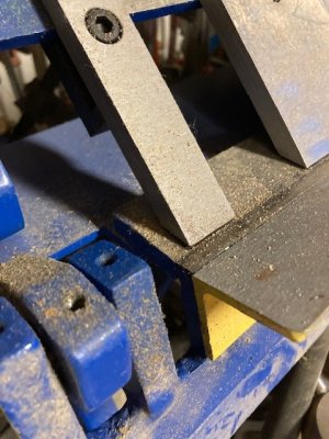
Anyway. The two vertical posts are too high so the fingers don't sit flat enough and the metal tends to bend up behind them because of the pressure. As mentioned by others the better quality ones have the fingers sitting much flatter to prevent that.
In my unit left vertical post is a tad too far forward too which results in the finger rail skewed and as a result the two fore/aft adjustments are on the opposite side of the peak which also results in a height issue.
The handle for clamping is drilled into the hub opposite the key as opposed to more horizontal like the better ones. That means it hangs over the edge of the table or the whole unit has to be raised.
And with all the free time on my hands over New Years I made a drawing of the unit.

Missing a few nuts and bolts. Handle in the correct spot. Fore/Aft adjustment levers work properly in the simulation.

1673051143732.png
 

Susquatch

Ultra Member
Administrator
Moderator
Premium Member
I know how you feel....

I figured we would lose some recent content, but I plowed ahead assuming I could pick up where left off.

FWIW, I recall your earlier post.

If it matters, soon we will all forget what we lost.
 

DPittman

Ultra Member
Premium Member
If it matters, soon we will all forget what we lost.
Yes I'm headed that way myself but right now thatvis not very comforting. Right now I can remember that I should know and remember things but that's as far as it goes sometimes. Man I hope this aging thing starts to slow down on it rapid decline pretty soon or else I'm going to be in trouble if and when I get "old".
 

Susquatch

Ultra Member
Administrator
Moderator
Premium Member
Right now I can remember that I should know and remember things but that's as far as it goes sometimes.

Yup, that's how it goes.....

I have an awesome advantage. My memory has never been worth a crap. So I don't really notice a decline in my memory as I get older. At least that's how I remember it......
 

Susquatch

Ultra Member
Administrator
Moderator
Premium Member
Speaking of memory problems, do you happen to remember who it was that needed photos of my 20 ton press?

I took a bunch of pics while the forum was down, but I don't remember who wanted them.
 

whydontu

I Tried, It Broke
Premium Member
I'm curious how the fore and aft pivot works on your brake. On mine, the eccentric is fixed to the upright by a locking set screw. The axle for lifting the fingers stays at roughly 6:00 at all times, just moves from 5:00 to 7:00 as adjustment for fore and aft. Does this make sense? I get the impression yours is organized differently.


IMG_2632.jpg IMG_2631.jpg
 

jcdammeyer

John
Premium Member
I'm curious how the fore and aft pivot works on your brake. On mine, the eccentric is fixed to the upright by a locking set screw. The axle for lifting the fingers stays at roughly 6:00 at all times, just moves from 5:00 to 7:00 as adjustment for fore and aft. Does this make sense? I get the impression yours is organized differently.


View attachment 29243View attachment 29245
Works exactly the same. The issue is that pivot points aren't in the same spot relative to the front edge. So put both levers at the same spot and at one end the fingers are in line with the edge and at the other end the fingers are set 2mm back.

Move the left lever to get that distance to be the same and the problem then is it's lifted that side up at bit too. Try to lower raise the other side to match and it moves fore/aft.

I had a great discussion on this on the Alibre Forum. One of the members actually made some videos to show how a system could be made that had only horizontal and no vertical motion. If this link works much of the info lost from this forum is there.
 

MashingMetal

Active Member
Please keep updating the thread as you are able to improve on things. i have the 24 inch PA version bought a few years ago. I am have problems clamping the sheet steel tight so when you do make the bend it does slide and ends up round.
Thanks!
 

YotaBota

Mike
Premium Member
Good job fixing things but all the mods and improvements makes me wonder if it wouldn't have been better to build one.
Yah, I know,, anybody can do it that way.;)
 

jcdammeyer

John
Premium Member
Please keep updating the thread as you are able to improve on things. i have the 24 inch PA version bought a few years ago. I am have problems clamping the sheet steel tight so when you do make the bend it does slide and ends up round.
Thanks!
Once I pick up a piece of 2.5" HRS the first thing I will do is update the clamping hub so the handle isn't in line with the key.
1673199369034.png
It will also angle outwards about 7 degrees so it clears the upper shaft.
1673199461438.png

The point to this is that without metal under the fingers the gap between the fingers and the platen should be about 1/2 the thickness of the material to be bent. Then when you clamp the material the lever should move to the lowest point where it would then start to go up again if rotation continues.

If your PA unit is like mine the lever is in line with the key and the handle wouldn't' even reach that point without the brake sitting higher. The handle would hit the table first. It's that point where it goes through the peak of the CAM that you get the most downward force.
 

MashingMetal

Active Member
Hi John, Here is another photo of mine with a finger removed, it looks like quite a bit different design, There are a couple problems with mine, I can see, you can’t adjust the clamping force great enough without running out of thread, The other issue is that the top can shift a bit after you have adjusted the offset for material thickness.
Mine definitely needs work too.
 

Attachments

  • FF5DE110-ED4A-4BD4-BEAE-8B1FE015C911.jpeg
    FF5DE110-ED4A-4BD4-BEAE-8B1FE015C911.jpeg
    79.2 KB · Views: 4

jcdammeyer

John
Premium Member
Hi John, Here is another photo of mine with a finger removed, it looks like quite a bit different design, There are a couple problems with mine, I can see, you can’t adjust the clamping force great enough without running out of thread, The other issue is that the top can shift a bit after you have adjusted the offset for material thickness.
Mine definitely needs work too.
Looks like at least your 45 degree bevel is closer in line with the platen. That's a good thing as it prevents the metal from curling up behind the finger.

Can you post a photo from the side with bending handles down and the fingers all the way down? This kind of view:
1673226081362.png

From what I can see your linkage is below the cam? Where the lever is on the above drawing puts the cam at the lowest point. In effect the fingers are resting on the platen and I can remove the bolt and slide the handle + cam hub off the shaft without any friction.

As I move the handle upwards it starts to push up on the turnbuckle assembly and lifts the fingers. If the metal I'm trying to bend is too thick then I can never get the handle down to the point where it is without metal inserted.

And yes, the problem with all of these systems is that the fore/aft motion also has up/down motion. So when you get that 1.5 metal thickness from the edge of the finger to the edge of the platen some of the crappy ones also end up lifting the fingers up. It means the adjustments interfere with each other and you need to go back and forth. Tedious.

Here's how the slotted fore/aft adjustment works:
HorizontalAdjustment.jpg
The orange CAM moves with the handle just like the existing systems. But instead of in a hole it's in a vertical slot. Never touches the top of the slot and the arm with the slot has a guide that runs on the cap that is concentric with the yellow center pin.

Now the orange cam moves the slot back and forth and since it never touches the top of the slotted hole the arm doesn't go up and down changing the height adjustment. The red guide prevents the arm from dropping on top of the cam. And once the yellow cover is screwed to the cam assembly the lever is locked in position. But the entire arm can still pivot around the yellow pin.

This will make it easier to adjust the fore/aft and therefore bend radius and also the clamping without as much interference. Because the fingers pivot through an arc depending on where they are when fore aft is adjusted it will change when they are pivoted.
 

jcdammeyer

John
Premium Member
Oh and usage. If I was going to bend 1mm thick metal I'd slip in 0.5mm metal and bring the clamp lever down to hold it just gripping by adjusting the turnbuckles at the toggle point. (lowest spot).

Then I'd adjust the fore-aft at this point for just under 1.5mm. Maybe 1.25mm. Then clamp in 1mm metal and measure to makes sure the slightly raised fingers that have gone up and backwards on the arc are now giving 1.5mm clearance.

If not, tweak fore aft. If it slips re-adjust for 0.3mm thick instead.
 
Top