-
Scam Alert. Members are reminded to NOT send money to buy anything. Don't buy things remote and have it shipped - go get it yourself, pay in person, and take your equipment with you. Scammers have burned people on this forum. Urgency, secrecy, excuses, selling for friend, newish members, FUD, are RED FLAGS. A video conference call is not adequate assurance. Face to face interactions are required. Please report suspicions to the forum admins. Stay Safe - anyone can get scammed.
You are using an out of date browser. It may not display this or other websites correctly.
You should upgrade or use an alternative browser.
You should upgrade or use an alternative browser.
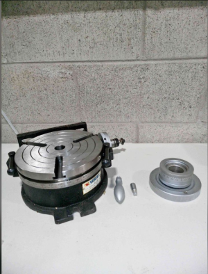
Vertex HV-8 rotary table
- Thread starter Aarknoid
- Start date
How do you clamp something square when there are only 3 T-slots? I would think 4 would make more sense.
I’ve pondered whether to buy a 3 or a 4 slot. Anyone have opinions on which choice and why?
If a good buy comes up second hand I don’t think it matters but if you had the choice what would you buy and why?
D

Indeed that is just the case.I think the major consideration with a RT is centering the table to the center line of the spindle. The work can be squared to the x or y with a test indicator.
I did a military "Advanced" Machining course where we spent likely 90 percent of our working time, setting up various rotary table jobs, and the first step, ALWAYS, was to confirm center alignment with the spindle. And Trig. We did three weeks of Trig, to the extent that a couple of us confessed to starting to dream triangles! LOL!
After that, anything that needed to be squared up was dialed in with indicators. If we needed a reference surface to work against, we clamped parallel bars to the table of the R/T, at 90 degrees to each other, and those could be used, along with gage blocks and the like, to perform various offsetting, with some degree of precision.
For various reasons, we also almost always added a center hole to the work piece, very carefully drilled and reamed, so we always had access to a point on the work that was supposed to be aligned with the center of rotation of the axis of the Rotary Table. This feature also became part of the means that the instructors were able to use some relatively simple measurements from edge of hole to edge of feature, to see if our work was sufficient to expectations. Like, when you made both a male and a female dovetail, not only were they expected to mate up reasonable well and smoothly, but the instructors would push a gage pin through the holes in the two parts to see how close to perfectly centered the parts were.
I would suggest that on as small a table as an 8 inch, three slots is going to work fine. You really don't have the kind of real estate on top of the R/T to be able to use all that many different hold down clamps.
If you were considering mounting a chuck of some sort, that would depend on the chuck's native mounting method requirements, if it was capable of being bolted through from the front. If you are making your own adapter plate, well, you run what you got, eh?
@Tecnico , I think the only difference would be versatility, unless the part you are working with needs either 4 or3 hold down clamps. 4 slots would give you more options I suppose.
Getting back to @Upnorth 's question regarding squaring up the work, you can do that with the table's function at any time.
Getting back to @Upnorth 's question regarding squaring up the work, you can do that with the table's function at any time.