• Scam Alert. Members are reminded to NOT send money to buy anything. Don't buy things remote and have it shipped - go get it yourself, pay in person, and take your equipment with you. Scammers have burned people on this forum. Urgency, secrecy, excuses, selling for friend, newish members, FUD, are RED FLAGS. A video conference call is not adequate assurance. Face to face interactions are required. Please report suspicions to the forum admins. Stay Safe - anyone can get scammed.

Theoretical Machinist Thread calculator

PeterT

Ultra Member
Premium Member
I've been using this website because it has an easy interface to compute thread parameters mores suited to machining. Recently I had to do some oddball threads & had the feeling some of the dimensions were off a bit. I chocked this up to devil in the details of min/max or root flat or their definitions or...

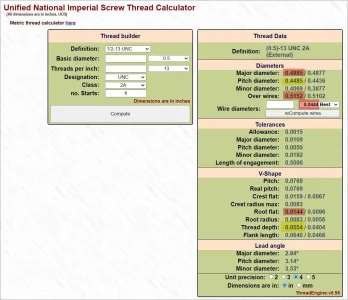
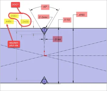
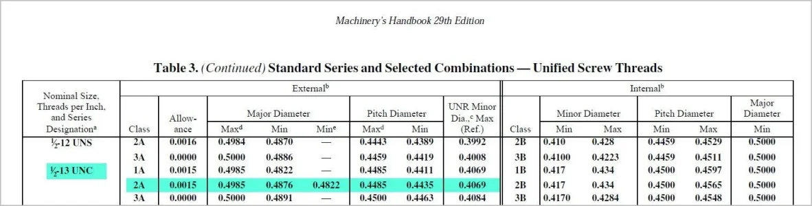
As a sanity check I CAD replicated a standard external thread using their parameters. If I use their defining parameters (pink shade) including their recommended wire diameter & MOW dimension, the rest of the parameters (yellow) drop out by default, but those do not agree to calculator values. Specifically the important parameters like resultant pitch diameter which is the target I have to hit in real life. If I switch things around & define the pitch diameter into CAD, I get a different MOW dimension. I pulled out Machineries handbook; the major dia & pitch dia agrees to calculator tool, but they don't really get into DOC for class of fit in a nice convenient format like the website calculator. Just wondering if anyone has similar experience or I'm missing something obvious? Pitch diameter + wire diameter measurements (alone) should circumnavigate any vee thread form variations for a defined thread class, no?


Attachments

  • EDT-24-08-2024 11.17.02 AM.webp
    EDT-24-08-2024 11.17.02 AM.webp
    130.9 KB · Views: 6
  • EDT-24-08-2024 11.21.38 AM.webp
    EDT-24-08-2024 11.21.38 AM.webp
    31.4 KB · Views: 6
  • EDT-24-08-2024 11.49.02 AM.webp
    EDT-24-08-2024 11.49.02 AM.webp
    66.2 KB · Views: 6
Peter, I'm not sure I understand your concern.

A few observations:

First, I cannot go to your reference website because it isn't secure. (http not https) Which raises all kinds of concerns separate to how it's results might differ from CAD or machinerys handbook. I won't use a non-secure website.

Second, you didn't discuss the overall diameter. As you know, you can cut almost any thread into any diameter if it fits. But the various dimensions do matter when you measure the thread. A 1/2-13 thread in your case is almost never really 1/2" diameter because of the crest shape. That's just it's nominclature. Is that perhaps where your difference is?
 
I'm not entirely understanding either. Is the question that the site gives a pitch dia of .4485 and you're getting .4486"?

It looks like your .4486 is measuring the distance between the two points where the wires touch the thread flank? That is not pitch dia and I think just a coincidence that the two are so close. e.g. you change the wire size, change the distance between those tangent points, but you wouldn't change the calculated pitch diam.

Here's a great reference for thread wires that can be a real lifesaver, like doing a 5 and 45 buttress thread ..... ugh, where to start with that? With this you can get through about anything, perhaps with some brain damage, but at least its possible :)

 
Last edited:
Fair point on the http/https. The site has some added information so I'll paste here. Most of it is standard terminology anyways. Everything I'm asking about is on the marked up screen grab

1724527057162.webp1724527123378.webp

Regarding diameter, its implied by the thread definition, 2A in this example. OD = 0.4985" = the same value specified in Calculator & Machineries Handbook & what I defined in CAD.
My point is that when I overlay their recommended wire diameter & specify their MOW diameter (& knowing thread is 60-deg) that combination fully defines the resultant pitch diameter because the wire is tangent to the Vee. My resultant PD = 0.4486 (MH=0.4485) so good enough there. So far so good.

But with all this in agreement using same parameters thus far, I cannot get their thread depth = 0.0554". I'm getting 0.0583, 0.0458" (depending on where I measure, basically I'm looking for a match). Its close but I would expect exact, especially when they calculate to 4 sigfig.
 
It looks like your .4486 is measuring the distance between the two points where the wires touch the thread flank? That is not pitch dia and I think just a coincidence

Ahhhh... thats right. I'm taking the tangent point of wire to flank but PD is related to the midpoint of the point to point sharp Vee segment (or something along those lines). I need to go back to the definition sketch. To be continued...
 
I cannot get their thread depth = 0.0554". I'm getting 0.0583, 0.0458" (depending on where I measure, basically I'm looking for a match).

I think you are getting messed up by the vagaries of the root profile which isn't really very important as long as it is within the limits of the fit class. In practice you will either cut a fairly sharp V with a blunt tip, a flat bottom, or a curved profile determined by the insert. I've never seen two identical inserts unless from the same lot. But again as long as they meet the fit tolerance, it Isn’t important. I'd fully expect different software to define different root profiles somewhat at the discretion of the program author just like the discretion of the insert designer who takes insert wear, manufacturability, and insert tooling wear into account in their design and tooling setups. For these reasons, it is my opinion, that the total thread depth is a rather meaningless number except in theory. That's the whole reason why we have thread wires and thread pitch diameter etc. These are repeatable meaningful numbers that are easily measured. How do you measure to a really sharp point that changes a few moments after the tool tip rapidly wears many thou anyway?

And of course, as you and @Mcgyver have both already noted, the reference for said measurement is everything.
 
@Susquatch yes, I'm aware of the thread profile root/crest variations & also the OD variations based on fit class. I made a brain fart error in my CAD implementation. I made the prescribed wire tangent to the thread flanks which is fine. But my error was measuring FROM those tangent points, which is not the pitch diameter as @Mcgyver spotted. Because the Cad/Calculator difference on this particular thread example was so close numerically, I just assumed round off error. I believe the pitch line is defined as mid distance of the theoretical Vee & that intercept is where pitch diameter is determined.

For the most part I turn the OD according to the desired fit class & increment the thread cutting until thread mic reads the PD (also correlated to fit class). If you don't have a thread mic you can use wires. If you don't have the recommended wires, you can use other wires (within limits). And that's where the online calculator is handy because you can input a different wire size & it will yield MOW dimension.

I think my generic A60 carbide thread inserts seem sharper nose than what the MH tables prescribe at the upper limits of their thread size, so that's where it becomes a bit iterative when it comes to actual machining. Because the OD is set, the cutting tool nose is set, all that remains is hitting PD. As you say, DOC is just the means of tracking infeed relative to resultant PD.

1724541876143.webp
 
I think my generic A60 carbide thread inserts seem sharper nose than what the MH tables prescribe at the upper limits of their thread size, so that's where it becomes a bit iterative when it comes to actual machining. Because the OD is set, the cutting tool nose is set, all that remains is hitting PD. As you say, DOC is just the means of tracking infeed relative to resultant PD.

Your explanation all makes sense to me. Your methodology will all work too.

As you probably know, I'm still new to using threading inserts and I have only used AG60 or A60 inserts to date. The next thread I do will probably use a topping insert for the said size - likely UN18 or UN16 depending on which job reaches prime first. So take this with a grain of salt.

Usually, with HSS. threading inserts, I use the 29.5 degree method to begin with and then I switch to a hybrid combination of crossfeed and compound to achieve a flat bottom profile for the root. I used to just cut semi pointed threads (rounded tip) at 29 5 all the way down till the thread mic was happy. The results were functionally fine, but I wasn't happy with them. I can be my own worst enemy at times.

If you are gunna use A60 inserts, I suspect you will end up doing the same thing because the tip is just too sharp to cut the best threads.

If I recall correctly, you plunge instead of going in at 29.5. So for you it will be easier to just use the cross slide till you reach depth, and then the compound to reach the thread size. You won't need to think about any hybrid movements.

Regardless, it's all good. It will all work. Glad you found your discrepancy.
 
I used to do the 29.5 compound thing & probably still would for bigger threads. Then I started noticing a lot of the insert catalogs were recommending straight in up to a certain thread size, which my work I was encompassing. Mind you that is a CNC spec. I'm violating most all of the carbide rules on my manual lathe at Tortoise speed anyway. Straight in makes for one plus; its basically like conventional turning. Infeed perpendicular, measure interim PD, set DRO, rinse & repeat. I prefer setups when I'm converging to what ideally should be the same target dimension because it flags any suspicious measurement before a boo-boo happens. So far so good on the 'sharp' nose, no broken tips. The toughest material has been 303 stainless but the threads were very nice. I do spring / cleanup pass or even two as I approach final. I guess I could run my carbide insert against the TCG diamond wheel to achieve whatever blunted nose, but at the finer threads I'm doing it basically doesn't matter.

I just watched a video where a guy sets compound aligned to bed axis & he has an infeed routine: in 3 + over 1... something like that. So that puts more load on leading edge side, kind of like the 29.5 method. But what intrigued me is once he was at depth, he started feeding directly along axis to achieve a specific root width. I thought that was interesting.

BTW, I'm sold on these AliExpress digital thread mics. Make sure to get the anvil kit! The 0-25 I bought from Shars is identical AFAIK so Ali mitigates higher cost, USA shipping & dinger fees.
Very accurate. Nice clutch feel. Button flip between IMP/MET. Or, zero datum reference a PD from a known reference thread & display difference as you turn. I think battery life is generally getting better on Chinese stuff but I take mine out if I think it will sit a while.

1724557923742.webp
 
But what intrigued me is once he was at depth, he started feeding directly along axis to achieve a specific root width. I thought that was interesting.

This is the method I described above. That's also what @thestelster does all the time. You must have missed all that discussion in several earlier threads.

It's probably what I will end up doing if I completely transition to using carbide inserts. I just not there yet. If i was faced with doing a critical threading job tomorrow, I'd use 29.5 and HSS. But I am playing with inserts and slowly adopting them. You can get a set of different full form pitch sizes at Accusize here:


What really slows me down in my transition is that I'd like inserts for aluminium. HSS let's me creep up on a dimension a thou at a time. Regular carbide doesn't like that. But I'd expect Aluminium inserts to be sharp enough to let me do that on steel. But so far I have not found a set that I can afford. I'd have to buy them individually from a big name. I might do that for 16 & 18 if I find them when I'm feeling adventurous, but I'm not normally ready to dive in that deep.

BTW, I'm sold on these AliExpress digital thread mics. Make sure to get the anvil kit! The 0-25 I bought from Shars is identical AFAIK so Ali mitigates higher cost, USA shipping & dinger fees.

I have not used digital thread mics. I have an Accusize Vernier thread mic and anvils that I like. And I think @thestelster is looking for anvils for a thread mic he got. Hopefully he will see your post above. If there is a chance they would fit it would probably be worth a try. Next time I'm talking to him I'll mention it.

I really hate that battery drain problem. I have an early mitutoyo digital caliper that does that all the time and it drives me bonkers. I bought a more recent one and it seems to be much better but still not perfect. I also have a really nice half tenths digital micrometer that does it and I do what you do and just remove the battery when not in use. A shame really!

All good stuff.
 
This is the method I described above. That's also what @thestelster does all the time. You must have missed all that discussion in several earlier threads.
Yes I saw it, thanks. His big lead screw. It flew over my head to advance cutter in both directions per feed. I thought it was just a final set of passes to open up the root width to final dimension/PD.

We have flogged the carbide turning inserts in other posts, but next time you're in the shop get the specs of the aluminum insert you are using. AFAIK you should be able to replicate that in many different form factors. That might be your problem if you're using big toolholders for example the may not offer that variant for steel in that form factor. I'm using CCMT & DCMT.

The 3 main parameters are #1 coating (which we already know = uncoated). #2 nose radius, typically r= 0.2, 0.4, 0.6 mm. Even the uncoated aluminum come in various 'r' variants. And #3 rake angle. This one isn't so obvious because it often is not referenced. But somewhere in my travels I have seen the inserts documented & aluminum are steeper as one would expect. I also suspect this is why aluminum inserts feel 'sharper'. I've always wanted to test this on one of those blade maker sharpness gizmos so its quantified. Certainly some badly made coated inserts have some round over effect, but (guessing) 90% of industrial inserts have some kind of coating so one has to assume they know what they are doing

So the fact that you are getting good results on carbide for aluminum is probably a combination of these parameters but may be weighted more one factor than another. You cant really know unless you vary them independently. My point is that CCMT & DCMT are spit cheap on Ali. Lately I've been sampling their newer flavors 'made for stainless' because they are so inexpensive to try. The geometry & coating looks a bit different but they cut both stainless & regular carbon steels better. I do use the aluminum inserts on steel occasionally too for finishing. They work fine but don't last as long. Mostly I don't see a huge benefit & don't want to mix them up so uncoated=aluminum (and bronze), coated = steel.

These are my original 'for stainless' DCMT inserts cutting 303 SS valves 0.001" (diametric) finishing passes. They go to lapping stage after this so it fits the job requirement +0.001".
I think they might even be 0.4 rad but would have to check. The newer ones for SS seem to cut a bit better but I haven't actually done them side by side on the same work piece.
1724606234692.webp
Ali aluminum showing different nose radius. I think the normal progression is 02,04,06,08 (mm). It seems to me even the chip breaker profiles are a bit different too but that might be what I have. Whether they vary the rake too I don't know.
1724606739399.webp
 
Back
Top