• Scam Alert. Members are reminded to NOT send money to buy anything. Don't buy things remote and have it shipped - go get it yourself, pay in person, and take your equipment with you. Scammers have burned people on this forum. Urgency, secrecy, excuses, selling for friend, newish members, FUD, are RED FLAGS. A video conference call is not adequate assurance. Face to face interactions are required. Please report suspicions to the forum admins. Stay Safe - anyone can get scammed.

Milling machine electrical question

05plsrt4

Member
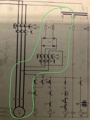
Im finishing up converting my milling machine to single phase and was wondering if anyone can explain this part of the original wiring diagram. Thanks.

It is a schaublin mill.

To me it seems like they are feeding 2 legs of the rapid motor with 80v DC? If this is true why would they do that? Or am I completely wrong?
 

Attachments

  • IMG_3706.jpeg
    IMG_3706.jpeg
    373.2 KB · Views: 30
The legend for the parts is
m3 - rapid motor
c2 - rapid contactor
e3 - fuses
n1 - diode bridge
c3 - mystery contactor
 
Parts of your drawing have been cut off.

However, I think you are reading the drawing incorrectly.

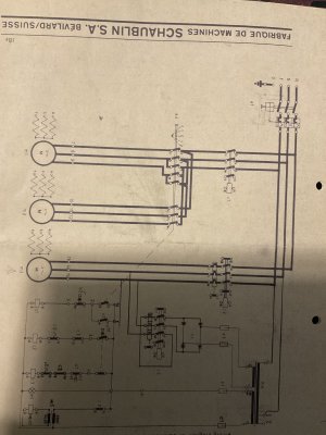
3ph power comes in at the top left and goes through some switches to the motor at the bottom left. Power for other components and the transformer are tapped off of the main power leads on the left to feed the transformer and other circuits on the right.

I don't know what your voltage is because it's missing on what I can see. But I would guess it's 3ph something (prolly 220 or higher).

I would NEVER switch a vastly superior 3ph motor to an inferior single phase one. I'd just go get a VFD to convert single phase supply to 3ph power for your machine.
 
I agree with Susquatch. The diagram clearly shows 3 phase power coming in (delta connection) and some power taps for some control or accessory circuits. The feed has to be AC and the lowest common voltage is 120 / 208. 347 / 600 is also a common 'low' voltage. There might be some DC components on your machine, but they aren't shown on this diagram.

3 phase AC motors are inherently more efficient than single phase ones. Unless the motors are pooched, I wouldn't replace them with single phase ones. If you only have single phase available, a VFD can fix that.
 
I need to run this by my Electrical Engineer friend. But this is my interpretation:

What you are seeing is the mains single phase feeding a rectifier through the contactor, back to a transformer providing DC bias.
- In this case, if the DC bias saturates the core, it will drop the voltage across the E1-E1output. This will in turn, starve C1 C2 C3 and d1. The C series shuts off power to each motor.

This appears to be protection from connecting the wrong voltage to the main terminals. Noe of the starter relays will function in this case.

The M5-D1 series seems to be a power-start-reset protection. Why it is behind a 550V-120V transformer is not clear to me, so that part is likely wrong.
 
In this case, with 3 separate 3PH motors, 3 VFDs will be needed, and the machine will need to be completely rewired. Not a problem for a competent electrician, but an easier solution is a rotary phase converter/transformer to deliver 550V nominal.

This a first for me. Normally, I would scoff at the idea of an RPC. But in this case, it is prolly the best path.

If it were mine, I'd still go with the 3 VFDs or just dump one or two of those motors.
 
The motors are 575/320v. I tried running them off a vfd. The large motors didn’t like if very much, the coolant pump ran off it fine. So i had to purchase 2 new motors. I also wanted to use the original switches. So I decided to just go single phase.

I dont have the room for a RPC and transformer so that option was out of the question. All the electronics in the machine cant handle (arnt rated) for the higher current when i lower the voltage so they would need to be replaced. I also wanted all the electronics to be inside the machine where they were originally placed.

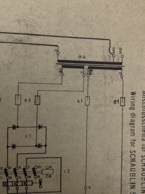
Im just finishing the conversion but do understand what the part in the first post is or if it is required. There are no dc components in the unit That i am aware of. And does the “80” at the transformer mean 80 volts? If they were feeding the transformer with dc voltage wouldn’t the contactor be installed in the opposite direction So the overload protection can do what it’s designed to do?
 
If they were feeding the transformer with dc voltage wouldn’t the contactor be installed in the opposite direction

No transformer ever runs on DC other than switched.

Please take a photo of this 80 you speak of. I doubt it's a voltage.

You can prolly run it on the original switches, but it will be a dogs breakfast - especially for the poor SOB who buys it next.

Hard to believe the big motor. Didn't like a VFD - unless there are things you are not telling us......
 
heres the ”80” All the other numbers im assuming are voltage.

The vfd was a techtop. The motor is a 4hp 550/320v 3 phase. When trying to run it it got very hot and made a loud buzzing noise. I was told that the motor was too old and not vfd rated. The other motor is a 1-1/2hp, made a loud buzz and spun very slow. They told me the same thing.

The machine was manufactured in 1963 i think.
 

Attachments

  • IMG_3708.jpeg
    IMG_3708.jpeg
    429.9 KB · Views: 12
The vfd was a techtop. The motor is a 4hp 550/320v 3 phase. When trying to run it it got very hot and made a loud buzzing noise. I was told that the motor was too old and not vfd rated. The other motor is a 1-1/2hp, made a loud buzz and spun very slow. They told me the same thing.
It is very tricky putting a 575V 50 Hz motor on a VFD designed for 48V60Hz. It can be done - by someone who is advanced.

*IF* you spend the money on 3 VFDS at 400$+ per VFD, then you can get the technical department to get you going. ***but not on cheap VFDs without technical support***
 
Somehow we have done it again! Another long conversation about electric stuff!

I'm sure that any explanations I make are not always clear, but I have 20+ years of facilities experience - sourcing from multiple power grids that are out of phase; and providing WHIP. Locations all over the world with wildly differing standards

Most computers are capacitive loads. All induction motors are inductive loads. Impedance matters, and lots can be done

I am not good at understanding what the colour, length shape etc the chips mean. I Juts don't have that experience / knowledge
 
So back to the original question…c anyone tell me what that is there for?
I tried to explain in post #6. Some transformers are wound to be voltage sensing: thus the DC 'injection' on the winding marked 80. My friend is in Scotland right now, but is on his way back 'real soon'. He needs to see the schematic, so please be patient, and we'll get back to you.
 
All 3 phase motors can be run on VFD's the only question is how far can you extend the RPM range. VFD rated motors (ie constant torque) are built to allow full torque from zero to beyond 60hz.

Remember VFD's let the motor think is at full speed, as it is dependent on the frequency.

The additional DC injection circuits now come out as the VFD does everything you need and uses DC injection if it is designed into the Unit.
 
Back
Top