• Scam Alert. Members are reminded to NOT send money to buy anything. Don't buy things remote and have it shipped - go get it yourself, pay in person, and take your equipment with you. Scammers have burned people on this forum. Urgency, secrecy, excuses, selling for friend, newish members, FUD, are RED FLAGS. A video conference call is not adequate assurance. Face to face interactions are required. Please report suspicions to the forum admins. Stay Safe - anyone can get scammed.

Machining a Curved Tee Nut - An Interesting Setup

carrdo

Well-Known Member
Hi All,

Time to do something I had ignored for decades.

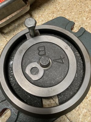
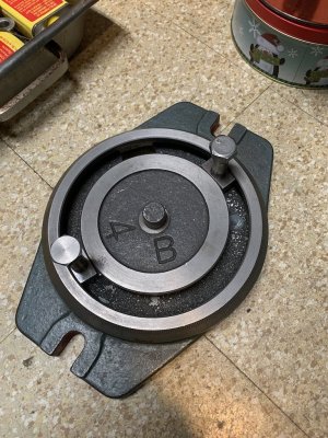
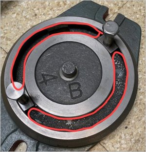
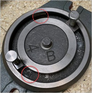
This involved machining a new curved tee nut to fit into the round tee slot in the swivel base of my most used milling machine vise. It is not too often that I need this swivel base but recently I did. I had employed the bodge of an upside down bolt as a substitute but it was both awkward and not that secure a fix. so...

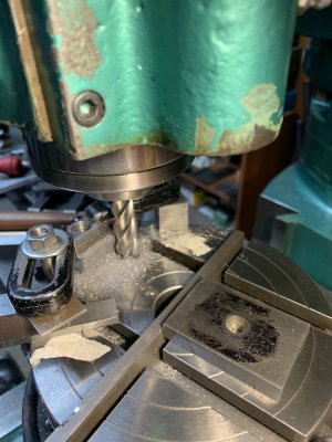
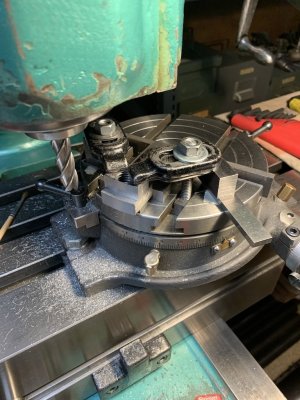
It was a lot more work than I ever anticipated. See the first two photos for what I am talking about.

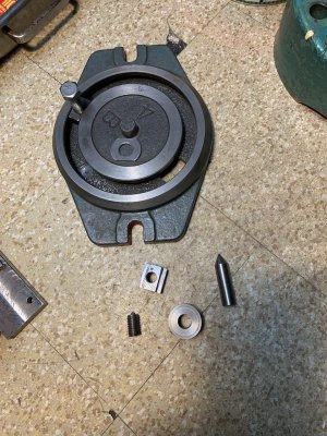
Not to go with a bodge this time I had to start by making some new parts for the setup needed. See photo 690. Can you guess what they do?

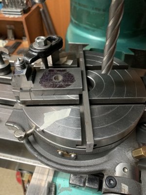
The problem is one has to align the threaded tee nut blank three different ways, i.e. it has to be set radially and central on the rotary table and it has to have the same radius as the vise base tee slot. Needless to say the tee slot blank has to be squared all around to start with and the rotary table centered under the spindle of the mill.

The last photo shows how the tee nut blank was set radially. The radial spacer also has to be square and machined to a length which will roughly result in the correct radius which, for this setup, was 70 mm as both my milling machine vise and my rotary table come from Japan. Fortunately, since this rotary table has two parallel tee slots one on each side of centre, I can use secondary spacers set from each side tee slot to accurately center the tee slot blank.

There also has to be a tertiary parallel spacer set under the tee nut blank itself and it will shortly become apparent why.

A lot of work for something so simple.

to be continued.
 

Attachments

  • 687 A Curved Tee Slot Nut.jpg
    687 A Curved Tee Slot Nut.jpg
    125.6 KB · Views: 22
  • 689 A Curved Tee  Slot Nut in the Circular Tee Slot of my Milling Machine Vise Base.jpg
    689 A Curved Tee Slot Nut in the Circular Tee Slot of my Milling Machine Vise Base.jpg
    225.1 KB · Views: 23
  • 690 Some of the Setup Parts.jpg
    690 Some of the Setup Parts.jpg
    256.5 KB · Views: 24
  • 691 Setting the Tee Slot Nut Radially.jpg
    691 Setting the Tee Slot Nut Radially.jpg
    142 KB · Views: 24
Last edited:
Hi All,

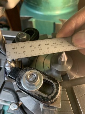
Setting the radius of the curve was from the center of the rotary table to the center of the round tee slot in the vise base = 70 mm utilizing the previously made pointed round pieces.

Since I don't have digital it was literally point to point as seen in photo 692. The outer and inner radii on the curved tee nut were milled just by moving the table of the mill longitudinally and by comparison to the existing curved tee nut. The only problem was the restrictiveness of the setup as I had to reposition the clamps several times (one at a time so as to not lose the settings).

On the inner curve, the parallel spacer under the part allowed one to mill down past the bottom of the tee nut slightly.
 

Attachments

  • 695 The Second Curved Tee Slot Nut Installed.jpg
    695 The Second Curved Tee Slot Nut Installed.jpg
    238.7 KB · Views: 15
  • 694 The Inner Curve Finish Machined.jpg
    694 The Inner Curve Finish Machined.jpg
    144 KB · Views: 14
  • 693 The Outer Curves Finish Machined.jpg
    693 The Outer Curves Finish Machined.jpg
    165.7 KB · Views: 15
  • 692 Setting the Tee Slot Nut Curved Inner and Outer Radii.jpg
    692 Setting the Tee Slot Nut Curved Inner and Outer Radii.jpg
    124.1 KB · Views: 15
Good job. I have the same system on my lathe compound. Another irritation is when I loosen the bolts to turn the compound, the T-nut would trip slightly on the access slot in the bottom. Chamfering the bottom corner of T-nut helped a bit, but eventually I made a nylon plug that goes in from the underside & keeps the slot floor the same elevation so it slides across. Another thing I did was make 2 kind of kidney shaped spacers that keep the T-nuts orientated 180-deg. On my lathe I'd locate the bolt into one T-nut & then have to swivel & hunt around for the second one. It was just made from scrap plywood but does the trick.
 

Attachments

  • EDT-18-12-2024 10.14.34 PM.jpg
    EDT-18-12-2024 10.14.34 PM.jpg
    19.4 KB · Views: 7
  • EDT-18-12-2024 10.18.28 PM.jpg
    EDT-18-12-2024 10.18.28 PM.jpg
    100.9 KB · Views: 7
Nicely done. Good use of the rotary table and tricky set-up.

When I had a need to make new curved T-nuts for a lathe compound, I bolted two oversized pieces of rectangular stock with a spoil shim underneath to a face plate on the lathe, 180* apart. The distance between them was set the same as the diameter of the curved T-slot. Then I used standard turning tools / techniques to form the T-nut shape.

If you need a lot of the same sized curved T-nuts (or a longer one with multiple holes, for example), just make a whole ring on the face plate and cut them off to whatever sector length you need them afterwards.

The radius of the curved T-nuts you can make is only limited by the swing of your lathe / face plate diameter.
 
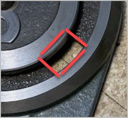
Another thing I considered & just didn't get around to trying is just make round profile T-nuts; easier to make on the lathe. When you look at the contact area it may not me horribly different than the curved profile block style, although if you are gronking this could come into play. A limiting factor is what likely a current rectangular feeder hole in the casting which might have to be enlarged with a drill to accommodate a round T-nut & that's where you have to pause & consider violating the machine. Actually that hole also limits the size of any T-nut which is why I think my stock ones are kind of undersized. I'm not worried about cracking the cast iron but I just wish it was larger.

I thought about making a ring out of a steel plate, part it into 2 equal segments, tap a hole in the middle of each. The idea being these could then be dropped straight into the slot. it would only take a few degrees of rotational scissor action float to provide sufficient contact area. The trick is would they find their home just by snugging the bolts. Bad sketch but hopefully makes sense.
 

Attachments

  • EDT-19-12-2024 9.52.17 AM.jpg
    EDT-19-12-2024 9.52.17 AM.jpg
    92.3 KB · Views: 0
  • EDT-19-12-2024 10.12.47 AM.jpg
    EDT-19-12-2024 10.12.47 AM.jpg
    122.2 KB · Views: 0
although if you are gronking this could come into play

As long as there are no gaps in the connection and the cast iron is in compression, it shouldn't be a big concern. Big no no to have gaps so the cast iron is in tension!

The idea being these could then be dropped straight into the slot. it would only take a few degrees of rotational scissor action float to provide sufficient contact area. The trick is would they find their home just by snugging the bolts. Bad sketch but hopefully makes sense.

I no like Peter. Too hard to get even loading and too easy to break the casting with loads so far from the bolt. It will also act like a scissor at the edge and shear the metal.

Everything I have like that has long oval heads. I like your first idea or @RobinHood best.
 
I no like Peter. Too hard to get even loading and too easy to break the casting with loads so far from the bolt. It will also act like a scissor at the edge and shear the metal.
I think you are right. Actually I had a brain fart. The intent was to make from a machined ring plate, but were much shorter in span, kind of a kidney shape. But turning into more work vs. a proper curve profiled T-nut. It never launched beyond the plywood prototype. The issue I saw (and it was on some cheesy import tool) the opening was too small, so the T-nuts were proportionately small, so it was stressing the CI for that reason. My lathe compound is somewhere in the middle. Not great but not bad. I think scraping the surfaces would be better time spent
 
Back
Top