Hi All,
Guys (and ladies)(I guess there are a few).
I don't know why I am telling you all of my secrets. Nobody taught me this; it was only learned through the school of hard knocks. It is probably one of the most difficult of all machining operations. There are many ways to do it wrong and only a few ways to do it right.
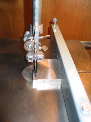
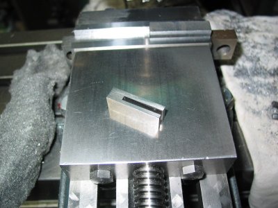
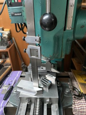
One project which I had was to produce a precision narrow deep slot. By precision I mean a slot that was truly rectangular, was not bell mouthed, was straight and on size to 0.001" or less with a smooth surface finish. The slot in question was 1/8" wide and 1-1/8" deep. It was for a replacement scriber carrier on a Starrett 6" vernier height gauge which I have used for decades. This height gauge is a beautifully made precision tool so do everything to keep it that way. Don't wave it around or drop it, bump or nick it by throwing it in with any other tools or metal pieces, keep it scrupulously clean and lightly oiled and it will last longer than you will. But I digress. It is not cheap and condition is everything but is it truly expensive if it will last more than a lifetime and as well keep all of its built in precision...?
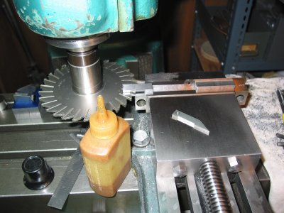
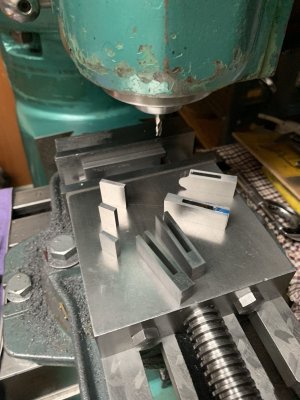
To start, material selection is very critical. No ordinary steel is right for this job. Starrett makes a special toolmakers steel called gauge stock which is a special alloy steel which has been heat treated (and then ground flat in various rectangular sizes) to virtually eliminate any internal stress so that the material does not move when machined even though on a few occasions I found that even this material bell mouthed a bit (about 0.002") when making these slots. To be fair though, it may not have been a true Starrett product as I have purchased other "gauge stock" products on occasion. 1144 Stressproof steel is a possible option but it only comes in round bars and I have not tried it.
Why any normal steel is unsuitable is because of the internal stress inherent in the steel due to surface cold rolling or cooling where the exterior of the steel cools first before the interior does. Theoretically, you need an infinite cooling down period to avoid the aformentioned condition but since this is not possible, other methods have to be employed. Cutting, shaping or bending simply redistributes these internal stresses but does not eliminate them.
to be continued.
Guys (and ladies)(I guess there are a few).
I don't know why I am telling you all of my secrets. Nobody taught me this; it was only learned through the school of hard knocks. It is probably one of the most difficult of all machining operations. There are many ways to do it wrong and only a few ways to do it right.
One project which I had was to produce a precision narrow deep slot. By precision I mean a slot that was truly rectangular, was not bell mouthed, was straight and on size to 0.001" or less with a smooth surface finish. The slot in question was 1/8" wide and 1-1/8" deep. It was for a replacement scriber carrier on a Starrett 6" vernier height gauge which I have used for decades. This height gauge is a beautifully made precision tool so do everything to keep it that way. Don't wave it around or drop it, bump or nick it by throwing it in with any other tools or metal pieces, keep it scrupulously clean and lightly oiled and it will last longer than you will. But I digress. It is not cheap and condition is everything but is it truly expensive if it will last more than a lifetime and as well keep all of its built in precision...?
To start, material selection is very critical. No ordinary steel is right for this job. Starrett makes a special toolmakers steel called gauge stock which is a special alloy steel which has been heat treated (and then ground flat in various rectangular sizes) to virtually eliminate any internal stress so that the material does not move when machined even though on a few occasions I found that even this material bell mouthed a bit (about 0.002") when making these slots. To be fair though, it may not have been a true Starrett product as I have purchased other "gauge stock" products on occasion. 1144 Stressproof steel is a possible option but it only comes in round bars and I have not tried it.
Why any normal steel is unsuitable is because of the internal stress inherent in the steel due to surface cold rolling or cooling where the exterior of the steel cools first before the interior does. Theoretically, you need an infinite cooling down period to avoid the aformentioned condition but since this is not possible, other methods have to be employed. Cutting, shaping or bending simply redistributes these internal stresses but does not eliminate them.
to be continued.
Attachments
Last edited: