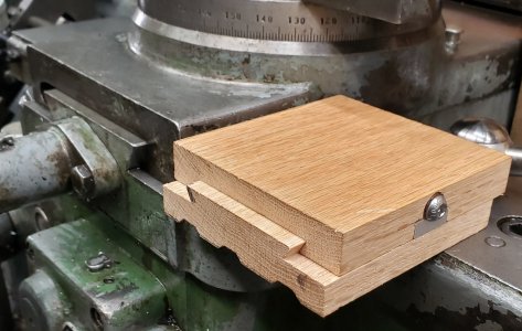
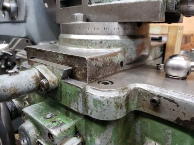
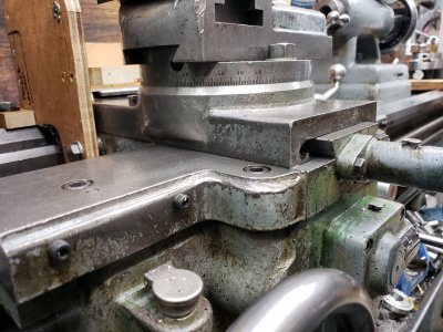
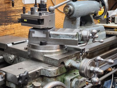
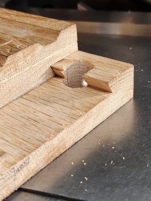
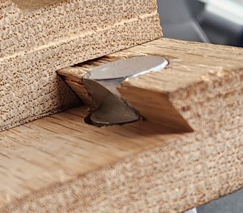
I have a carriage lock, which helps when parting or facing. But no cross slide lock. I'm thinking it will be handy when drilling or reaming using the toolpost, interrupted cuts, or when using the toolpost grinder. My lathe has a full length gib on the left. I read some posts about drilling a hole and using a ball bearing backed up by a set screw. I don't like the thought of damaging the dovetail. So, here's what I'm experimenting with. Of course wooden mock-up. It takes very little force to lock up it up solid. I tried to measure it, but the minimum my torque wrench goes is 10 in.lbs. , and its way less than this.
-
Scam Alert. Members are reminded to NOT send money to buy anything. Don't buy things remote and have it shipped - go get it yourself, pay in person, and take your equipment with you. Scammers have burned people on this forum. Urgency, secrecy, excuses, selling for friend, newish members, FUD, are RED FLAGS. A video conference call is not adequate assurance. Face to face interactions are required. Please report suspicions to the forum admins. Stay Safe - anyone can get scammed.
You are using an out of date browser. It may not display this or other websites correctly.
You should upgrade or use an alternative browser.
You should upgrade or use an alternative browser.
Lathe Cross-Slide Lock
- Thread starter thestelster
- Start date
VicHobbyGuy
Ultra Member
That looks like a lot bigger mod to the cross slide than just adding an extra 'locking screw' (or two) to squeeze the gib. Perhaps I don't understand what I'm looking at?
I would put whatever locking device you end up going with on the gib side. This forces the movable part of the cross slide hard against the straight side of the dovetail. More repeatable that way.
If you put the lock on the non-gib side, you might get “rocking” of the cross slide if you don’t have perfect gib mating surfaces.
If you put the lock on the non-gib side, you might get “rocking” of the cross slide if you don’t have perfect gib mating surfaces.
mickeyf
Well-Known Member
The atlas mill I just sold had the style of gibs that were adjusted with four screws each, each having a locking nut. Except that one of each set of four had either a knob or a handle for tightening it down to lock that axis. It worked fine. If you have the style of gib that adjusts by means of a single screw at the end, and is tapered, you'd need a different approach.
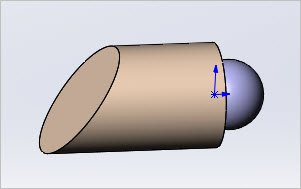
I like the design aspect that your shoe has the matching angle to the dovetail (agree with @RobinHood) gib side. But a potential concern that you have a relatively big notch removed to accommodate. Hopefully the material wont stress relieve there. My (Taiwan 14x40) slides have a threaded hole drilled through which intersects the gib strip. Its very primitive. The screw bites away at the gib strip with pecker marks & you can see movement on the DRO while tightening. So I made this shoe out of brass & Loctite a bearing ball in the end. The bolt was center drilled so it just pushes axially on the ball with no other movement. You could put a pair of them in the side & double your clamping pressure.
Attachments
On my cross-slide, there are no adjusting screws on the side which push on the gib. Instead a have a long steel tapered gib which is adjusted by a screw from the front (closest to the operator).
Attachments
Hi Peter, having the lock on the head side was a safety concern of mine as well. In terms of a shoe in a hole like you described, might not give me enough bite on the dovetail without using excess force. My cross slide is 13.5" long, so notching it out 1" or so for the lock shouldn't reduce the overall strength or integrity of the unit.Interesting. I would not be fond of reaching on the chuck side to engage the lock. Better on the tailstock side. Still. I wonder if the threaded hole with a floating shoe idea could work?
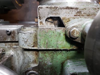
Here are the locks on my Colchester Master 2500.
Note: the lock can be positioned for vertical engagement as shown in case of the cross slide (green ellipse). In your case, the locking screw would still be on “the danger side, ie the chuck side, but that is because the gib is on that side. On the Colchester, the gib is on the TS side.
The red ellipse shows how the lock works on the compound.

Hi Robin, fantastic, thanks for that. So, that screw for the pad is left hand thread? And it's pushing on the gib which pushes on the the dovetail? Will it not deform the gib a slight bit in that when you unlock the lock there's uneven resistance moving the cross-slide?Here are the locks on my Colchester Master 2500.
Note: the lock can be positioned for vertical engagement as shown in case of the cross slide (green ellipse). In your case, the locking screw would still be on “the danger side, ie the chuck side, but that is because the gib is on that side. On the Colchester, the gib is on the TS side.
The red ellipse shows how the lock works on the compound.
View attachment 25179
No, both are standard SHCS.So, that screw for the pad is left hand thread?
The vertically oriented one for the cross slide (green) is threaded into the locking pad (#73094). It pulls up on it. The slight upward motion of the pad‘s wedge puts a corresponding slight inward pressure onto the gib. This in turn locks up the cross slide solid against the non-gib side.
The horizontally oriented SHCS for the compound (red) passes through a clearance hole in the pad (#73098). It threads into the movable part of the compound casting. The little wedge you see on the pad pushes against the gib, which in turn get pushed against the dovetail. This reduces any slight clearances on either side of the dovetail to zero, thus locking the compound solid.
Yes.And it's pushing on the gib which pushes on the the dovetail?
Technically yes.Will it not deform the gib a slight bit in that when you unlock the lock there's uneven resistance moving the cross-slide?
It takes very little torque on the SHCS to lock it up solid as the clearances (should just be enough for a close sliding fit along all the surfaces) between the locking pad, the gib and the dovetail are extremely small - so not much slack to be taken up (ie deflection).
As soon as the pressure is released, the sliding clearances are re-established and things operate without any binding force.

Oh for God's sake!! Yes of course. Sometimes I have an idea in my head and am blinded by the alternatives. Thank you you for your effort, and patience with me.
Hi Peter, having the lock on the head side was a safety concern of mine as well. In terms of a shoe in a hole like you described, might not give me enough bite on the dovetail without using excess force. My cross slide is 13.5" long, so notching it out 1" or so for the lock shouldn't reduce the overall strength or integrity of the unit.
My cross-slide is 14" long, longer than yours by 1/2". I wouldn't worry about the lost length either. Mine has a very simple allen key grub screw that bears on the Gibb which is on the tailstock side. The grub screw is flat while the Gibb is sloped at that spot. So the grub screw grabs tightly. But I don't like it. I'll probably either make a tapered (cone shaped tip) Gibb screw or notch my Gibb with a flat in that area. I kind favor putting a flat spot on the Gib. That way, there is zero chance of messing up the bearing surface on the Gibb with screw marks. Less chance of moving the Gibb as the lock screw gets tightened down too. And last but not least, a new Gib would cost WAY LESS than a replacement cross slide.
So ya, I lean toward notching the Gibb.
Although I'm glad it is on the tailstock side, it will be in the way of a future DRO Scale. That said, I'm still not happy with a scale in that area because I frequently bump my tailstock in there when I drill. This whole issue needs a lot more thought and maybe a novel dro scale solution of some kind. Perhaps up on top of the cross slide.
Although it looks REALLY COOL, I'm not real fond of the idea of a cam screw behind the scale. Way too probable that it will wear as time passes and need re-indexing just when you need it most. Murphy is not leaving town until long after my wife buries me and my junk out back.
Edit - I wrote the above over the course of 2 hours in little bursts while we picked up grandkids. So I didn't see the posts above until after I posted. I like @RobinHood's solution. But my Gib lock screw is much lower (in line with the Gibb) and I don't want to put in a second screw. I'm not even sure there is room above the Gibb. So I still prefer to mill a small flat on my Gibb as described above.
Last edited:
Well, today, I decided to get to this cross-slide lock project.
The main reason I want to do this is because I use the carriage to do most of my drilling and reaming, and there is the slightest shift from zero in the x-axis when I start to cut. No more than 0.001", but it bugs the #$%& outta me.
Also I'm sure it will help during interrupted cuts.
I will be installing a lock ala Cholchester that @RobinHood has showed me on earlier posts, and it will go on the left side so that it pushes on the gib.
Stay tuned!! I hope I don't firetruck this up.
Attachments
I still can’t quite picture what @RobinHood is laying down, unclear how the pad fits in the cross slide. But pictures will speak volumes!
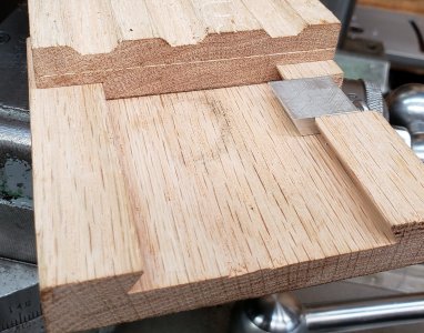
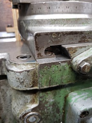
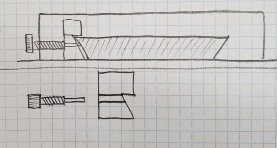
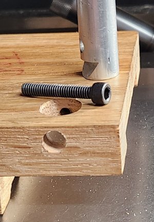
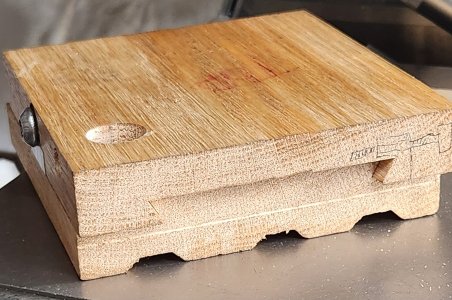
So, of course I always make a mock up from wood to test my design or, in this case Cholchesters', and see how to incorporate it into my machines.
And this worked out well, and pretty simple. Now to do it for real.
And this worked out well, and pretty simple. Now to do it for real.
Attachments
And this worked out well, and pretty simple. Now to do it for real.
I assume that all that is upside down.
You gunna put a handle nut up top?
I should look at how my lock works. I've never really thought about it before. I don't use it very often.