• Scam Alert. Members are reminded to NOT send money to buy anything. Don't buy things remote and have it shipped - go get it yourself, pay in person, and take your equipment with you. Scammers have burned people on this forum. Urgency, secrecy, excuses, selling for friend, newish members, FUD, are RED FLAGS. A video conference call is not adequate assurance. Face to face interactions are required. Please report suspicions to the forum admins. Stay Safe - anyone can get scammed.

Half-Nut Engagement

Darren

Ultra Member
Premium Member
Actually, I've done it before. For a 4-start thread. On my lathe any 1/4 thread, you must engage the half nuts at the same number on the thread chasing dial.

So for instance, if I select a 5 3/4 thread on my QCGB, since I have to engage at the same number: 4 (4-start) x 5 3/4tpi = 23tpi. So calculate what the depth of cut is for a 23tpi and cut to the depth engaging at each of the numbered lines.

Easy peasy, and perfect. The only thing you have to worry about us your flank clearance.

I like that thread dial chart so I decided to 3d print my own for my Emco lathe.

Screenshot (1).png
 

Susquatch

Ultra Member
Administrator
Moderator
Premium Member
I like that thread dial chart so I decided to 3d print my own for my Emco lathe.

You are a bad influence. I really like that!

Did you have to use both black and white filaments to print that?
 

Susquatch

Ultra Member
Administrator
Moderator
Premium Member
Actually, I've done it before. For a 4-start thread. On my lathe any 1/4 thread, you must engage the half nuts at the same number on the thread chasing dial.

So for instance, if I select a 5 3/4 thread on my QCGB, since I have to engage at the same number: 4 (4-start) x 5 3/4tpi = 23tpi. So calculate what the depth of cut is for a 23tpi and cut to the depth engaging at each of the numbered lines.

Easy peasy, and perfect. The only thing you have to worry about us your flank clearance.

I seem to have missed this post. I replied to Tom's question too. I think that caused me to jump over yours.

I would not have the courage to do that. The math of figuring all that out to be sure I didn't mess it all up would have sent be scurrying for the compound solution I gave him a post or two after yours.

I've read your solution several times now. It still isn't obvious to me how you figured out which thread dial marks to use.

and cut to the depth engaging at each of the numbered lines.

How did you know to do this?

Or did you just experiment and assume that each of the four numbered lines would increment the thread spacing by 1/4?
 

historicalarms

Ultra Member
I know on some Hendey lathes that is how they do it. Steve Sum
My Henday doesn't have a threading dial nor does it have accommodations to mount one that I have seen so dials must have come into being sometime after 1916.

The incomplete operators manual that I have been able to download has a reference to threading using the forward/reversing clutch...they claim "threads can be picked up at anytime with use of the clutch"///I have yet to give this a try to see how it is done or works to their claim, Ill have to wait till spring makes my shop an environment I want to stay in.
 

Bandit

Ultra Member
I am not going into where, when, what mark to use on the thread dial. If the mark on the dial does not line up with mark on the body when engaging the lead screw, possible wear of the pinion gear or possible poor alinement when assembled, wear is very likely on an older, much used lathe. One of my lathe is like this. When I got it, the threading dial was engaged with the lead screw. I removed it for cleaning. The pinion gear showed a large amount of wear and that for some time had not been fully engaged with the lead screw, about 1/2 of each tooth had been worn away for 1/2 the tooth depth. How much running of the lathe to do this, no idea. But a dirty lead screw, chips etc. and possible little lube, in hand with not being disengaged when not threading, has worn it a lot.
Just something to check once in a while.
 

RobinHood

Ultra Member
Premium Member
has a reference to threading using the forward/reversing clutch...they claim "threads can be picked up at anytime with use of the clutch"
That would make sense if there is single point dog clutch to reverse the lead screw. Once the half-nuts are engaged, they stay engaged and just the fwd/rev control of the lead screw is used for threading.
This system does not lose synchronization with the spindle.
Steve’s Hendey in the video has that feature. Hardinge (& its clones), some Standard Moderns and I’m sure others have it as well.
 

Susquatch

Ultra Member
Administrator
Moderator
Premium Member
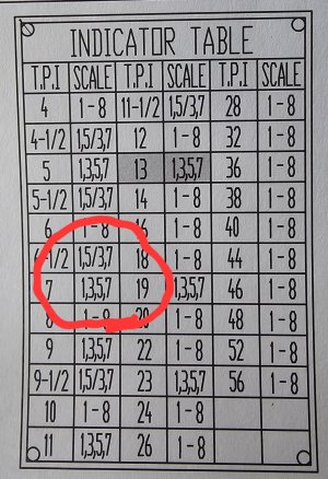
I have a related question. I have an 8tpi lead screw. This is my thread dial chart.

20240115_162659.jpg

I'm not sure what the two entries mean. Pretty sure the bottom one means you can use position 1 or 3 or 5 or 7 interchangeably.

But what does the one above that mean? Does it mean you can use either 1 and 5 interchangeably or 3 and 7 interchangeably but not 1 and 3 or 1 and 7? In other words you have to choose the first pair or the second pair but once chosen you can't change pairs.
 

RobinHood

Ultra Member
Premium Member
But what does the one above that mean? Does it mean you can use either 1 and 5 interchangeably or 3 and 7 interchangeably but not 1 and 3 or 1 and 7? In other words you have to choose the first pair or the second pair but once chosen you can't change pairs.
I believe that you have interpreted that correctly.

I wonder….

If you were to switch pairs (intentionally, or by mistake), would you cut a 2-start thread? Here is why I believe that could be possible…
Look at, for eg, 4.5TPI. You can use 1 and 5 OR 3 and 7. Let’s look at 9TPI. You may use 1, 3, 5, and 7. Nine is double 4.5. So if you WERE to use the other pair, you would probably ”split” the intended 4.5TPI thread by putting another helix in between, essentially creating a “9TPI“ thread as far as the helix spacing is concerned OR, I would call it a 2-start, 4.5TPI thread. This hypothesis would have to verified of course… (more time in the shop for you).
 

Susquatch

Ultra Member
Administrator
Moderator
Premium Member
This hypothesis would have to verified of course… (more time in the shop for you).

I'm mostly in the house right now drawing up wiring diagrams getting ready for the big motor swap. I'm converting the lathe from 220 single phase to 220 three phase with a VFD. Once I start the conversion I won't be doing any lathe work till its done. I'll most likely be miserable for that period. So abolutely ANY excuse to go out and play is always welcome!
 

Susquatch

Ultra Member
Administrator
Moderator
Premium Member
I believe that you have interpreted that correctly.

I wonder….

If you were to switch pairs (intentionally, or by mistake), would you cut a 2-start thread?

Thank you! What a beautiful excuse to play!
 

thestelster

Ultra Member
Premium Member
Let me explain the purpose for me to try to find a way to do multi start and how I did it.

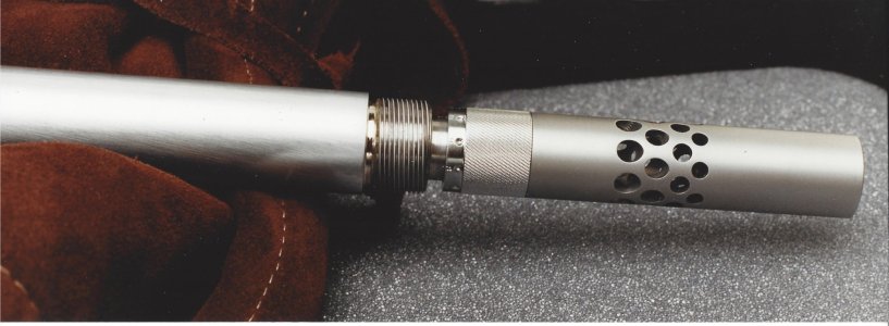
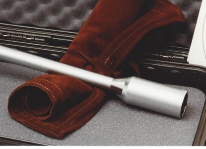
I had a customer who wanted a tuning muzzle brake installed. Easy peasy. But, he was concerned about the additional noise that occurs with a muzzle brake. What he wanted me to make is a tube that went around the muzzle brake that would push noise forward., we'll call it the Cone of Silence, ok this is a little more difficult. But he also wanted to be able to put it on and take it off quickly so that he could adjust the tuner.

Hence the idea of multi-start thread. After asking all my machinist buddies, this was about 20 years ago, so before I knew you guys, and before my internet days, they were giving me suggestions, like advancing the compound axially, or turning between centers but still having the 3 jaw chuck in position, using a lathe dog, and the tail of the dog to be driven by the jaw of the chuck, then going to the next jaw, cut the thread, go to the next jaw, cut the thread. 3 jaws equals 3 start thread. But I didn't like those methods. So I spent hours looking and thinking and reading. I then a light bulb happened. EUREKA!!!

Photo_2024-01-15_171723.jpg


Photo_2024-01-15_172710.jpg


Photo_2024-01-15_172314.jpg
 

Susquatch

Ultra Member
Administrator
Moderator
Premium Member
Very nice! Makes good sense too.

I did something similar. I wanted a two stage adjustment on the rear leg of my rifle rest. One for fast changes in height and one for fine tuning. So I made a two stage screw. An inner screw with one fine thread for fine tuning, and an outer double thread for fast adjustments. It works really well and can be quickly adjusted with just two fingers on a large knurled nut.

When I moved the thread start for the double thread, I just moved the threading tool in the tool post. That was about 25 years ago. At that time, I didn't know any other way.
 

thestelster

Ultra Member
Premium Member
I'll use the new plate that @Darren made, which is a copy of the plate on my lathe.

It says that if I need to cut a thread with 1/4 tpi, I need to close the half-nuts at the same numbered line. So if I need to cut a 5 3/4 tpi thread (which my lathe is capable of doing, I have to close the half-nuts at either 1 or 2 or 3 or 4.

Ok, sure if I use a 5 3/4 tpi thread for the Cone of Silence, it will come off and go on very quickly, but the depth of that thread is 0.094" that's way too deep for our purpose.

Lets say for now we want to cut 5 3/4 tpi. We set our QCGB to 5 3/4, and we start our threading at #1 on the thread chasing dial. We do that first pass, disengage our half-nuts, go back to the beginning, and wait until the #1 comes around again (because, remember to cut a 1/4 thread we have to close the half-nuts at the same number always), and when it does we engage.

Now if we close our half nuts at the #1, make a cut, and the next pass we close the half nuts at the #3 (which is the number directly opposite #1 on the thread chasing dial), we will have made a cut in between the previous thread. So now we have two threads being formed, so now we have 2 x 5 3/4 tpi threads, which is 11.5 tpi. The depth of cut for 11.5 tpi is 0.047". So if we close our half-nuts alternating between the #1 and the #3 on the chasing dial, and cut to a depth of thread of 0.047", we have a perfect 2-start thread.

But that was still too deep.

So lets keep our QCGB set to 5 3/4 tpi but this time we close our half nuts at the 1 and 2 and 3 and 4 marks on the chasing dial. We have now made 4 x 5 3/4 tpi thread = 23tpi. A 23 tpi thread has a depth of cut of 0.024". So now we have a 4-start thread with 23 tpi. And at 0.024' depth of thread, that works perfectly for my purpose.

I have even made an 8 start thread, by using the lines in between the numbers of the chasing dial. (just as an experiment)

The only issue when cutting multi-start threads is that you must have enough clearance on your threading tool so that it doesn't rub on the tread due to the greater helix angle. For carbide inserts you can get angled shims which sit below the threading insert. For HSS you have to grind the relief.

Does this work with every lathe? I really don't know. But my lathe has a lead screw of 4tpi, I can only hypothesize that any other lathe with the same lead screw pitch will work similarly, but you have to try it out.

This is absolutely the fastest, easiest method of cutting multi-start (at least 2-start and 4-start).

But, my lathe only has 4 different pitches with 1/4 threads (2 1/4, 2 3/4, 3 1/4, 5 3/4 tpi), so I am limited at the pitches I can cut. If I was asked to do a 3-start, then I have to use a different method.


20240115_063721-jpg.42967
 

RobinHood

Ultra Member
Premium Member
Thanks @thestelster for your explanation.

Since we are talking multi-start threads, I decided to check the manual for my Colchester Master 2500. My documents are off the internet as my lathe did not come with a manual. I have two versions of the manual, one newer than the other. The one manual does not address multi-start threads at all! (the one I have been referring to myself since I got the lathe). Turns out the other version does! I just stumbled on it this evening…

Here is what Colchester says:

752155AB-FEE9-40C4-ABB1-4CD3B616D32B.jpeg

I guess Steve‘s Hendey with a driver gear tooth count of 36T has more options for multi-start threads than my Colchester with 40T. That’s probably why Hendey chose 36T in the first place…
 

thestelster

Ultra Member
Premium Member
Thanks @thestelster for your explanation.

Since we are talking multi-start threads, I decided to check the manual for my Colchester Master 2500. My documents are off the internet as my lathe did not come with a manual. I have two versions of the manual, one newer than the other. The one manual does not address multi-start threads at all! (the one I have been referring to myself since I got the lathe). Turns out the other version does! I just stumbled on it this evening…

Here is what Colchester says:

View attachment 42982

I guess Steve‘s Hendey with a driver gear tooth count of 36T has more options for multi-start threads than my Colchester with 40T. That’s probably why Hendey chose 36T in the first place…
I would think #1 or #2 would be way easier than #3, no?
 

Darren

Ultra Member
Premium Member
Another way of indexing a multi start thread would be to hold a center in the chuck jaws, turning between centers, with the drive dog driven by the jaws. Use a 3 jaw for 3 start threads, 4 jaw for 2 or 4 start. You can easily re-index the drive dog for the other threads.
 
Top