• Scam Alert. Members are reminded to NOT send money to buy anything. Don't buy things remote and have it shipped - go get it yourself, pay in person, and take your equipment with you. Scammers have burned people on this forum. Urgency, secrecy, excuses, selling for friend, newish members, FUD, are RED FLAGS. A video conference call is not adequate assurance. Face to face interactions are required. Please report suspicions to the forum admins. Stay Safe - anyone can get scammed.

Timing belt and critique drive concept please

slow-poke

Ultra Member
I'm now thinking about how I'm going to add CNC capability to the knee joint of my A1S mill.

I want to use a similar 2.4Nm continuous torque 7.2Nm peak ac servo, except this one has an integrated brake. I have a beefy double nut ballscrew waiting in the corner.

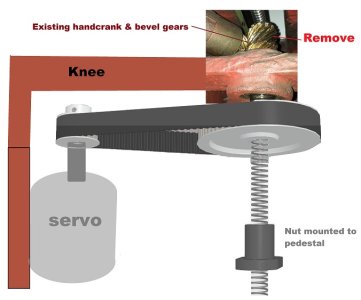
From my measurements and reading about knee conversions it seems I will need a 3:1 torque multiplication to be on the safe side. Aim is to have < 0.001" error, so driving through the bevel gears is not an option. There appears to be plenty of room to mount this servo just inside the front edge of the knee and then drive the new ballscrew via a suitable timing belt as shown in the concept drawing below. The servo moves with the knee and the upper end nub of the ballscrew simply pushes up against the existing bearing (more likely on a spacer that fits in the existing bearing).

Can anyone spot any obvious problems with this concept?

Suggestions for suitable timing belt that will accommodate about 20+ Nm of torque?
IMG_KneeGear_s.jpg
 
Last edited:

Maker Mike

Well-Known Member
Premium Member
Not sure if it is something you would consider, but this is an option. Go to about 5 minutes into the video to see what he did with the Z axis.
 

slow-poke

Ultra Member
Thanks for the link, I actually watched that one a while back, a couple of interesting points:

1) the gas struts, I'm hoping to avoid that by using a servo with an integrated brake, basically the servo is locked up mechanically whenever it's not being commanded to move, that includes with no power.

2) fortunately it appears I have room to fit the servo towards the front of the knee so I don't need to chop a hole in the knee. The belt and pulley setup will be near identical except to the front instead of the side.

I will be sizing up the servo mounting bracket today. I found a suitable (probably overkill) AT10 belt and for initial test fit and perhaps a couple of up and down test runs I will print the pulleys (found step files at McMaster-Carr).
 

jcdammeyer

John
Premium Member
@jcdammeyer has powered knee on his mill I believe.
Oh boy oh boy one of my favorite subjects!
Where to start...
Here's my timeline.
I pulled the shaft that turned the pinion gear which turned the acme screw that lifted the table assembly. I made a new mount for the shaft at the handle end to have bearings instead of bushings and at the pinion end made an adapter that holds a ball bearing and was able to move the pinion closer for less backlash. Attached is a PDF of the drawing.

Then mounted a toothed pulley and size 34 500 oz-in stepper motor and ran it from my Electronic Lead Screw for positioning and motion. Worked fine but very very very slow before it would lock up. Some torque testing and upgraded to about 1200 oz-in and 65VDC power supply. Now I got 25 ipm motion.

Better. Here's a short video of Y and Z motion. Y is a DC Servo, UHU Servo drive. Z is 1200 Oz-In Stepper with Gecko Stepper Driver.
It's been run with a BeagleBone Black, MachineKit (LinuxCNC).

Still not fast enough though. When I started having DC servo problems on the X axis where it would lose position I changed the XY to AC servos from Bergerda. Very happy. A while later upgraded to an AC Servo (750W) on the knee. Still with the same 3:1 reduction. Now 150 ipm.

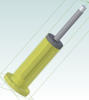
Meanwhile during that whole time I had the idea to get rid of the right angle drive and change to turning a ball screw directly. This photo shows the ACME style where the screw is turned and the bronze nut is held in the post.

KneeACMEScrew.jpg

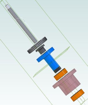
But what if I made a new post out of some pipe and a base designed now to hold a ball nut assembly.


ExplodedKneeBallScrew.jpg

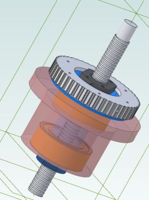
Now mount a motor onto that pedestal and turn the pulley which turns the ball nut. That moves the ball screw up and down and the top is anchored to the table.

KneeBallScrew.jpg

The only other thing it would need is some sort of brake that holds it in place when power is removed or the weight of the table will spin the nut and motor assembly.

So that's where I am at the moment.
 

Attachments

  • KneeAssembly34.pdf
    972.3 KB · Views: 2

slow-poke

Ultra Member
Some progress on the CNC knee project. 3D printed a couple of timing pulleys for trial fit and reality check, who knows, perhaps they will be strong enough to actually make the knee go up and down while I find some affordable metal ones? Hmmmm I could probably scrounge a couple of ~3:1 timing pulleys off an engine in the wrecking yard, finding a belt to match might be tricky though.

Next up order a timing belt, and make a ballscrew nut mounting block.

A few pictures of bits and pieces......
IMG_1083.JPG IMG_1084.JPG IMG_1088.JPG IMG_1089.JPG IMG_1090.JPG IMG_1095.JPG IMG_1098.JPG IMG_1099.JPG
 
Last edited:

jcdammeyer

John
Premium Member
Some progress on the CNC knee project. 3D printed a couple of timing pulleys for trial fit and reality check, who knows, perhaps they will be strong enough to actually make the knee go up and down while I find some affordable metal ones? Hmmmm I could probably scrounge a couple of ~3:1 timing pulleys off an engine in the wrecking yard, finding a belt to match might be tricky though.

Next up order a timing belt, and make a ballscrew nut mounting block.

A few pictures of bits and pieces......
View attachment 48332View attachment 48333View attachment 48334View attachment 48335View attachment 48336View attachment 48337View attachment 48338View attachment 48339
As I recall the biggest issue with the 3D printed timing belt pulleys on my mill knee was that eventually they started cracking. A set screw on the key that doesn't loosen puts tension on the print. I'd have to dig the old ones out to see if I can figure out what else was wrong. I think they were also noisy and hard on the rubber belt.
 

slow-poke

Ultra Member
As I recall the biggest issue with the 3D printed timing belt pulleys on my mill knee was that eventually they started cracking. A set screw on the key that doesn't loosen puts tension on the print. I'd have to dig the old ones out to see if I can figure out what else was wrong. I think they were also noisy and hard on the rubber belt.
That's not surprising, the small one is keyed to the shaft, it might survive long enough fo proof of concept. The larger one is even more iffy, it will have to be mated to the ballscrew shaft with set screws.

IF I can get the knee up and down a few times, will consider them a success.

Thanks for your input.
 

jcdammeyer

John
Premium Member
I originally started with a 500 oz-in Size 34 stepper motor and an Engine CAM I think from a Honda 1.5L.

That gave me about 3:1 and wasn't enough. I upgraded to a 900 oz-in (or maybe 1200?) and then it gave me about 25 IPM up. No counterweight on the knee which would have really helped I think.

Then I started 3D printing when I got the 750W AC Servo. The pulley was referenced to the round part of the shaft and the square part that the crappy handle went on became the seat for the set screws. I tried various insert and pulley styles and ratios.

1717086998581.png

This was all back in 2019 and 2020. I imported a STEP file of the target pulley.
1717087580548.png
Then did the cutting and trimming to create the basic pulley shape for 3D printing. A lot faster and used less material than doing the entire pulley each time.
1717087640778.png
 

slow-poke

Ultra Member
Our AC servos are likely close in terms of torque IIRC 2.4Nm continuous and 7.2 intermittent.

What style belt and pulley did you settle on?

I printed 3:1 AT10
 
Last edited:

jcdammeyer

John
Premium Member
Here's my motor: The 80SM-M0320MAL. I'm running 25T on the motor and 80T on handle shaft. It's 1:1 on the bevel gear to the 0.25" pitch acme screw. So 3.2 turns for 1 turn of the lead screw or 0.25".

In LinuxCNC:
# 250 line encoderx4=1000x3.2:1 reduction pulley / 0.25" per Turn
STEP_SCALE = 12800.0

Although rated motor current is 3A, when I run the knee up at 120 IPM (max speed) the Drive Current Display shows a max of 2.1A so odds are I could probably change pulleys to get 150 IPM but 120 IPM is friggen scary enough.
1717110240939.png
 

slow-poke

Ultra Member
John,
Your servo is a bit more powerful than the one I plan to use. I'm reasonably confident the one I have should be up to the task with ~3:1 ratio.

Do you recall what belt type your using: HTD, GT3, something else?
Sort of looks like 5mm pitch?
Width 20mm?

I'm thinking of using 25mm wide AT10 belt, however is somewhat overkil.
 

jcdammeyer

John
Premium Member
John,
Your servo is a bit more powerful than the one I plan to use. I'm reasonably confident the one I have should be up to the task with ~3:1 ratio.

Do you recall what belt type your using: HTD, GT3, something else?
Sort of looks like 5mm pitch?
Width 20mm?

I'm thinking of using 25mm wide AT10 belt, however is somewhat overkil.
Even with your lower power and 3:1 I imagine you can still achieve 120 ipm. My belt is 15mm wide.
1717118560399.png
 

slow-poke

Ultra Member
John,

I'm using this servo, it is more expensive than the some of the others however I wanted a brake for the knee:

Ball screw pitch is 5mm.

HTD belt is interesting, I actually have a decent sized 15mm wide HTD pulley and I'm contemplating using it. During my Google research I read somewhere that HTD belt style are optimized for power transfer and are not ideal for positioning systems and another fellow suggested 25mm wide AT10 style, however he stated that AT10 is a bit overkill. Looking at design torque graph for the 5mm HTD it looks like it would be fine even at low RPM for servos similar to ours. I would think that any positioning errors due to stretch would be corrected by the closed loop aspect of LinuxCNC.

Are you using a lead screw or ball screw for this axis?

I have found on the X and Y axis, if I don't have very little backlash, LinuxCNC (using the linear scales not the servo encoder) wants to hunt at the destination trying to get the error < 0.001" I needed to use double nut ball screws and matched angular contact bearings to stop the hunting. Perhaps better optimized servo settings would allow sloppier backlash however I lack the servo tuning expertise to accomplish that so I brute forced it with better bearings.

Are you closing the loop with the servo encoders or linear scales? Did you experience any closed loop hunting?

I will post results as the parts roll in and I progress.
 

Attachments

  • T6M80-750H2B3-M17S.pdf
    185.9 KB · Views: 2

jcdammeyer

John
Premium Member
John,

I'm using this servo, it is more expensive than the some of the others however I wanted a brake for the knee:

Ball screw pitch is 5mm.

HTD belt is interesting, I actually have a decent sized 15mm wide HTD pulley and I'm contemplating using it. During my Google research I read somewhere that HTD belt style are optimized for power transfer and are not ideal for positioning systems and another fellow suggested 25mm wide AT10 style, however he stated that AT10 is a bit overkill. Looking at design torque graph for the 5mm HTD it looks like it would be fine even at low RPM for servos similar to ours. I would think that any positioning errors due to stretch would be corrected by the closed loop aspect of LinuxCNC.

Are you using a lead screw or ball screw for this axis?

I have found on the X and Y axis, if I don't have very little backlash, LinuxCNC (using the linear scales not the servo encoder) wants to hunt at the destination trying to get the error < 0.001" I needed to use double nut ball screws and matched angular contact bearings to stop the hunting. Perhaps better optimized servo settings would allow sloppier backlash however I lack the servo tuning expertise to accomplish that so I brute forced it with better bearings.

Are you closing the loop with the servo encoders or linear scales? Did you experience any closed loop hunting?

I will post results as the parts roll in and I progress.
I'm still on ACME screws as I have 42 other projects on the go...
The intention was to rebuild the knee to do direct drive like you are doing but turn the ball nut leaving the end of the lead screw fixed. (Msg #5 in this thread).
X and Y are also still ACME with 0.2" per Rev. Changing over is a big project and for now I use the backlash compensation in LinuxCNC. It's not ideal but for my level of work good enough.

Because I went with the MESA 7i92H to initially maintain parallel port compatibility for running both MACH and LinuxCNC I don't have enough inputs to close the loop with the encoder outputs And because I initially started with DC Servos that had 250 line encoders I configured the Bergerda drive to divide the motor encoder signals so that the steps per rev remained the same.

ie. even though the encoder is 2500 PPR (10,000 quadrature) the number of steps to make it turn one rev is 1000 matching the DC Servo.

I went that route because stock MACH PC parallel port couldn't step faster than that. When I moved my USB SmoothStepper over then I could do faster stepping. As well the MESA 7i92H is FPGA driven so it too can do higher step rates. But unless I change my Break Out Board accessing the encoders for closed loop is a non-starter.

I couldn't figure out from the StepperOnline information if the 24V brake signal is required to release the brake or enable the brake. It looks like it needs 24V to allow motor to turn since it's mentions power failure.
 
Last edited:

slow-poke

Ultra Member
John,

Regarding the brake, that's correct it was not immediately obvious from the documentation. Energize to move, so default power-fail or off is locked up.

Thanks for the info on the belts and pulleys it open up some options.
 
Top