• Scam Alert. Members are reminded to NOT send money to buy anything. Don't buy things remote and have it shipped - go get it yourself, pay in person, and take your equipment with you. Scammers have burned people on this forum. Urgency, secrecy, excuses, selling for friend, newish members, FUD, are RED FLAGS. A video conference call is not adequate assurance. Face to face interactions are required. Please report suspicions to the forum admins. Stay Safe - anyone can get scammed.

Jswain's active projects

Jswain

Joe
Figured I would make my own thread as I'm always tinkering in the shop. Be forewarned I am a very amateur machinist :p

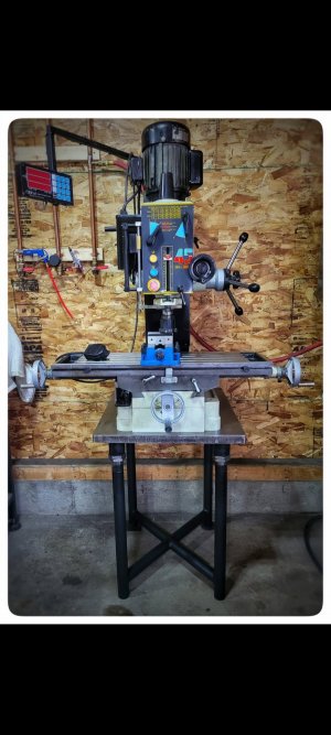
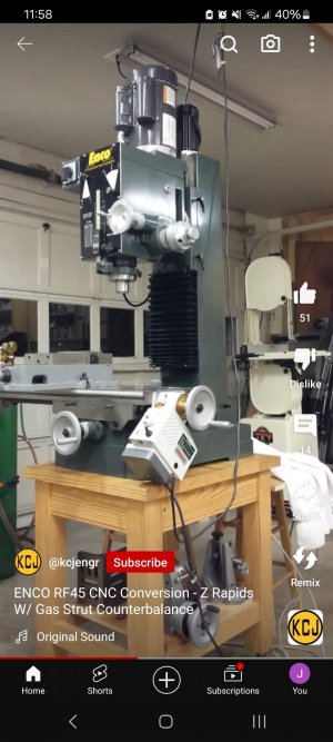
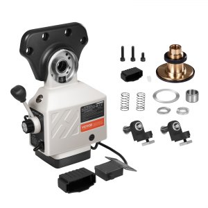
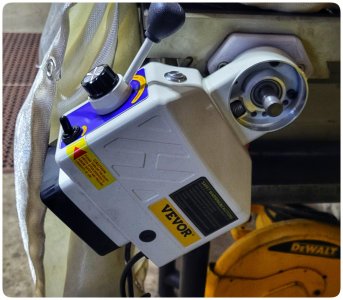
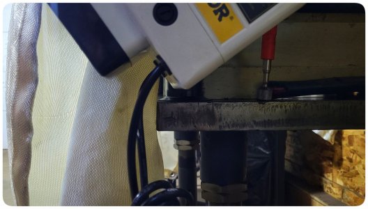
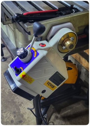
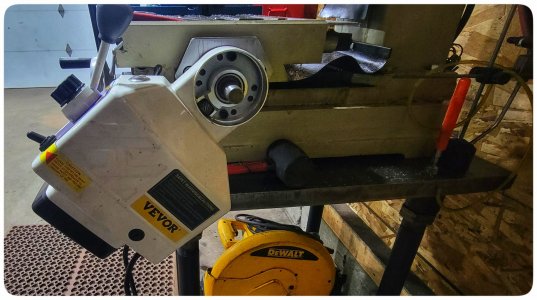
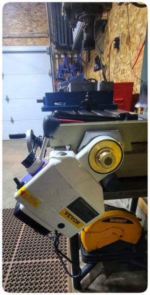
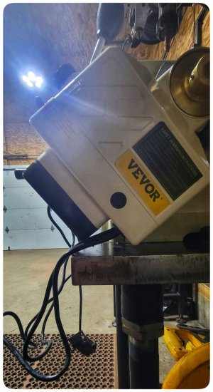
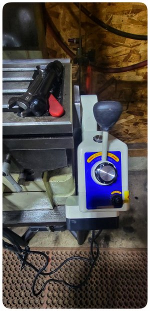
First project is adding one of the cheap vevor power feeds to my RF45 mill. Of course I did not splurge for the more expensive bolt on unit, why make it easy?

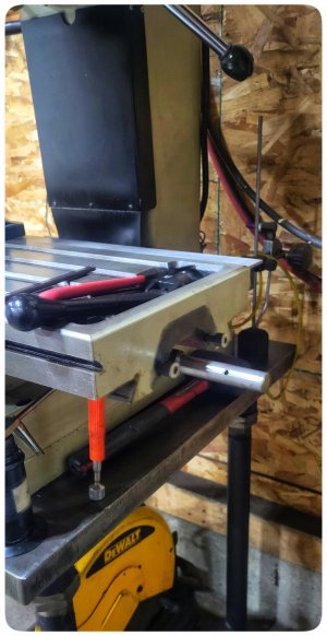
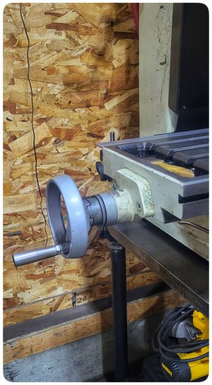
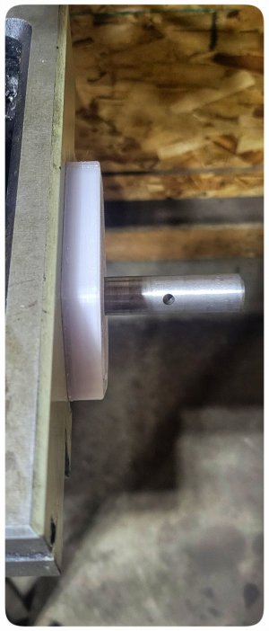
I started by swapping the x axis lead screw end for end, as well as the thrust bearing was moved to the left so I can install the power feed(hopefully) on the right, clocked clockwise enough to clear the table.

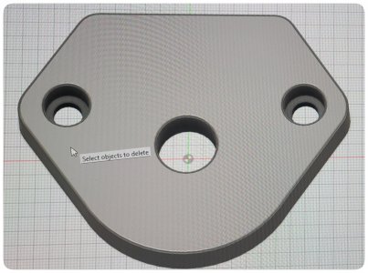
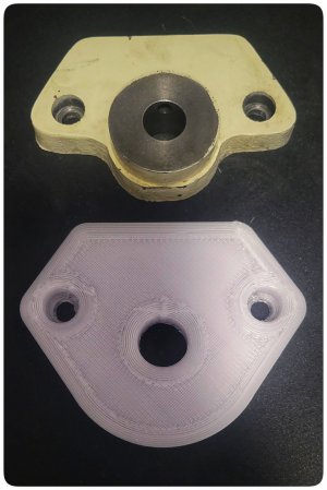
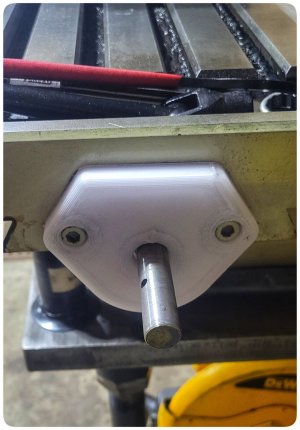
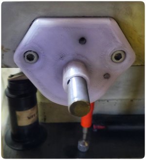
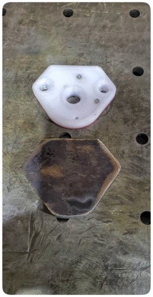
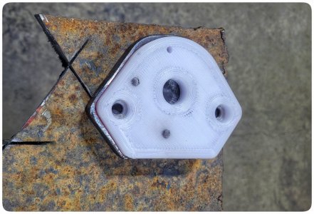
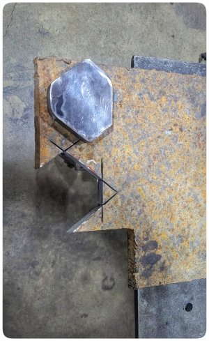
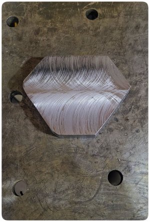
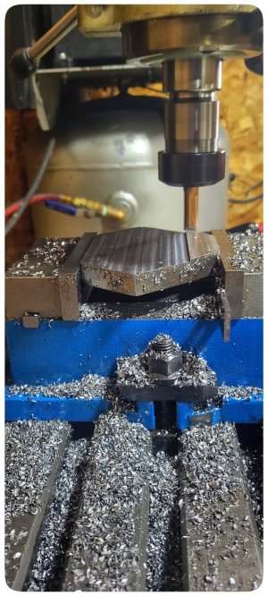
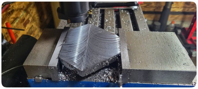
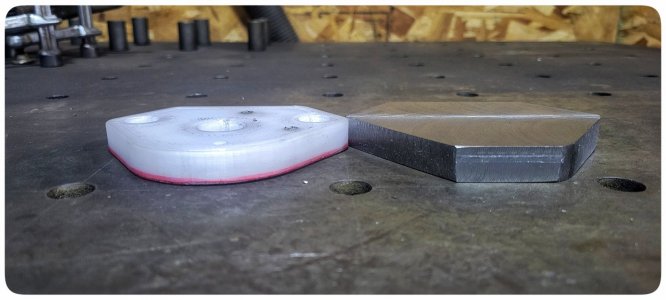
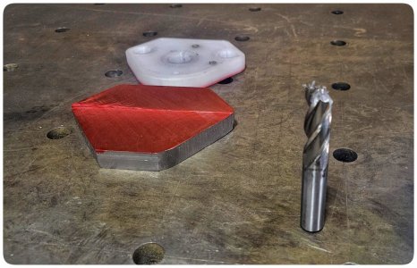
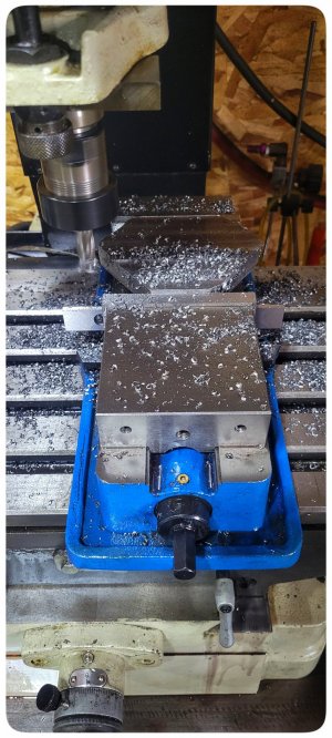
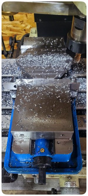
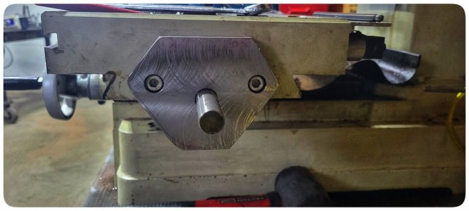
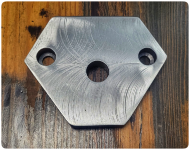
I used the cast iron lead screw support I removed to measure & make an adapter in fusion360 which is on the printer now. Once I figure out how much to clock the power feed I will drill & tap it for the mounting screws.

Plan is to 3d print whatever I will need to make it happen, then I will make the parts out of steel or aluminum. Looks like I will need to make a bushing for the bearing, bore & part the brass gear, and drill it for some set screws. Similar to how @YYCHM & @David_R8 attached theirs except on the other side.
 

Attachments

  • Screenshot_20231231_000041_Photos.jpg
    Screenshot_20231231_000041_Photos.jpg
    288.6 KB · Views: 32
  • 1000005575-01.jpeg
    1000005575-01.jpeg
    328 KB · Views: 33
  • 1000005574-01.jpeg
    1000005574-01.jpeg
    476.6 KB · Views: 22
  • 1000005573-01.jpeg
    1000005573-01.jpeg
    655.9 KB · Views: 33

Jswain

Joe
I believe I will need to extend the lead screw with an adapter if I want to mount a handle, will have to see when it's altogether how much room I have left.

I'm 100% ok without it, but if I can make it happen easy enough I will


This is the power feed I went with, pretty sure it's the cheapest/smallest one
 

Jswain

Joe
Fit up is pretty good, centre hole is slightly off but I plan to leave this oversize so it doesn't touch, will try to perfect it when I make it out of metal though.

Filament is clear PETG. 100% infill so hopefully I can locate & tap the power feed holes enough for a trial.
 

Attachments

  • 1000005581-01.jpeg
    1000005581-01.jpeg
    357.7 KB · Views: 16
  • 1000005583-01.jpeg
    1000005583-01.jpeg
    437.7 KB · Views: 16
  • 1000005584-01.jpeg
    1000005584-01.jpeg
    262.8 KB · Views: 16

Jswain

Joe
Bored out the gear & parted off the excess(with a band saw). Drilled & tapped for 3x m6x1 holes, and she is alive. I will get some grub screws to replace the m6 bolts but of course I couldn't wait.

It did push the gear down the shaft once, whether I didn't have the bolts tight enough or maybe I need to file some flats on the leadscrew like @David_R8 ?

Now to remake the plate & bushing out of metal, steel likely because I have some that should work.


Attachments

  • 1000005603-01.jpeg
    1000005603-01.jpeg
    507.1 KB · Views: 7

Jswain

Joe
Why buy materials, when you can make a huge mess in your clean shop;)

Think I'll get the 3 holes drilled out tomorrow, cover it all in sharpie then scribe it and clamp it in the mill and twiddle it down to size. After I make the bushing then I'll mark and drill the 6mm holes for the power feed.

I'll probably have to thin it down some too as it's 3/4 and would ideally be 1/2, so I should have left the rounded part square for clamping but that's a future me problem to figure out. Maybe once I get the top milled flat I will mill a flat in the bottom to clamp in the vise for facing both sides?
 

Attachments

  • 1000005616-01.jpeg
    1000005616-01.jpeg
    501.3 KB · Views: 5
  • 1000005615-01.jpeg
    1000005615-01.jpeg
    511.8 KB · Views: 5
  • 1000005614-01.jpeg
    1000005614-01.jpeg
    560.5 KB · Views: 5

Jswain

Joe
Milled 2 flats to hold the part in the vice then faced the one side. Flipped it over and took out the majority(~.170) with a 1/2 hss endmill, until I snapped it that is. Finished off with a 12mm carbide endmill & then took a .005" cut with the brazed carbide face? Mill.

Surface finish leaves a lot to be desired. I was feeding everything by hand so maybe a good portion of the reason? I did not trust the plastic enough to use the power feed, but probably would have been fine.

Marked it out with some sharpie so I can layout the holes and stopped for some lunch.

Starting to bear a resemblance!
 

Attachments

  • 1000005623-01.jpeg
    1000005623-01.jpeg
    645.4 KB · Views: 16
  • 1000005628-01.jpeg
    1000005628-01.jpeg
    445.5 KB · Views: 22
  • 1000005630-01.jpeg
    1000005630-01.jpeg
    406.1 KB · Views: 20
  • 1000005633-01.jpeg
    1000005633-01.jpeg
    279.2 KB · Views: 16
  • 1000005635-01.jpeg
    1000005635-01.jpeg
    517.9 KB · Views: 16

Jswain

Joe
I need to pay attention & learn feeds/speeds/DOC.

For the 1/2" hss endmill I was using 480rpm, .060" doc and feeding it fairly quick, chips weren't changing color at all

12mm carbide endmill I went up to 960rpm, and about the same doc & feed, same thing with chips, tho they looked smaller then the ones from the hss

For the I believe it's 2 - 7/8" ish brazed carbide face mill one the first side with .010" DOC I used 480 rpm, gearbox was fairly loud. On the second side I used .005" DOC and went up to 960rpm, gearbox was much quieter.

Couple photos of the chips from the hss & carbide endmills. Was using rapidtap for lube for the hss, nothing for the carbide and clearing all the chips between runs.
 

Attachments

  • 1000005625-01.jpeg
    1000005625-01.jpeg
    435.7 KB · Views: 14
  • 1000005627-01.jpeg
    1000005627-01.jpeg
    473.1 KB · Views: 14

Susquatch

Ultra Member
Administrator
Moderator
Premium Member
Starting to bear a resemblance!

First and third photos look a bit like my butt in the mirror.......

PS - Wife thinks my behind is handsome so that is not a shot. All good!

Nice work.

Agree on the cause of the broken endmill. My practice is all roughing is done conventionally - learned that the hard way. I only do climb milling when I can lock the axis solid and then only if I have no choice.
 

Jswain

Joe
Just have to remake the bushing tomorrow out of steel & figure out the limit switch mount.

Seems slightly quieter mounted to the steel, probably lined up better with the leadscrew.

I may drill an additional 2 holes so I can clock it flat if needed.
 

Attachments

  • 1000005653-01.jpeg
    1000005653-01.jpeg
    411.3 KB · Views: 9
  • 1000005655-01.jpeg
    1000005655-01.jpeg
    400.1 KB · Views: 10
  • 1000005659-01.jpeg
    1000005659-01.jpeg
    348.1 KB · Views: 9
  • 1000005658-01.jpeg
    1000005658-01.jpeg
    370.4 KB · Views: 9
Top