• Spring 2024 meetup in Calgary - date Saturday, April 20/2024. discussion Please RSVP Here to confirm and get your invitation and the location details. RSVP NOW so organizers can plan to get sufficient food etc. It's Tomorrow Saturday! you can still RSVP until I stop checking my phone tomorrow More info and agenda
  • We are having email/registration problems again. Diagnosis is underway. New users sorry if you are having trouble getting registered. We are exploring different options to get registered. Contact the forum via another member or on facebook if you're stuck. Update -> we think it is fixed. Let us know if not.
  • Spring meet up in Ontario, April 6/2024. NEW LOCATION See Post #31 Discussion AND THE NEW LOCATION

very stiff tailstock quill

curmudgeon

(Steve)
Grrr, the tailstock quill on my Grizzly G0602 10x22 is making me cranky. Extending/retracting the quill is so stiff that it is effectively unusable for drilling.

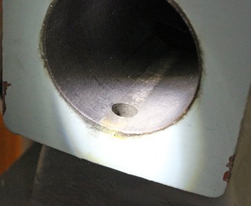
Here's a pic from the manual:
1680318112353.png

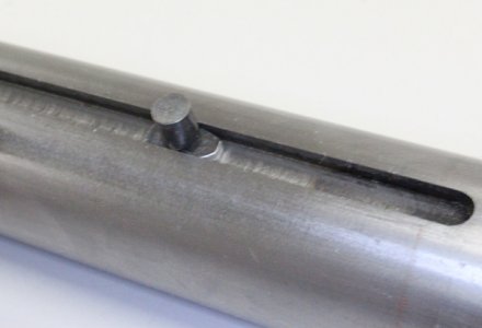
There's a slot along the backside of the casting, and the quill lock lever squeezes the casting around the quill. With the help of a mallet I can force the quill out of the casting. Neither the outside of the quill nor the bore of the casting is scratched up.

By tapping a wedge into the front of the slot in the tailstock, I can easily insert the quill about 1/2 ways in, but after removing the wedge the casting springs back to a "too tight" fit. It's as if the quill had been removed and the guerilla tightened the lock lever as tight as possible and left it that way for a decade.

I would love to spring it open so that it slides nicely, but I am super worried about cracking the casting.
- how worried should I be about using a wedge to open up the slot?
- would it be smarter to try and hone the bore of the casting?
- are there better options?

Thanks!
 

DavidR8

Scrap maker
Administrator
Moderator
Premium Member
Since you can extract the quill I'd measure the ID of the tailstock with a bore gauge.
I personally wouldn't try and wedge it as you risk cracking the casting.
I'd measure it with a bore gauge to figure out where the diameter becomes constant and them maybe hone it out with a cylinder hone?
 

Darren

Ultra Member
Premium Member
A dti is going to be your friend. Check for a bent quill first by chucking it and indicating. Don't use a wedge. Bad bad idea on a casting.

Unless you have a dial bore gauge, you could take the TS housing to a machine shop and have it checked. You may be able to line hone it on your own lathe if its just a machining flaw.

Has it always been stiff? Or just all of a sudden?
 

Bandit

Super User
Is there a slot/groove to stop the quill shaft from turning when moveing in or out? If so, may be burr, chip, buildup in groove or on dowel riding in groove, could be standing taller then should be also. Maybe polishing quill could help, remember, easier to make a quill, then bore out and sleeve the tail stock body if damaged. Have had locks not release right if forced too tight also.
 

curmudgeon

(Steve)
Since you can extract the quill I'd measure the ID of the tailstock with a bore gauge.
I personally wouldn't try and wedge it as you risk cracking the casting.
I'd measure it with a bore gauge to figure out where the diameter becomes constant and them maybe hone it out with a cylinder hone?
OK - no more with the wedge
I'm thinking a brake cylinder hone would work?

A dti is going to be your friend. Check for a bent quill first by chucking it and indicating. Don't use a wedge. Bad bad idea on a casting.

Unless you have a dial bore gauge, you could take the TS housing to a machine shop and have it checked. You may be able to line hone it on your own lathe if its just a machining flaw.

Has it always been stiff? Or just all of a sudden?
I've only had the lathe for a few months and the quill was awful the first time I tried to use it. I don't have a DTI but I hope a v-block and dial indicator can substitute for confirming the quill is not bent.

Is it possible the lock is not releasing properly?Maybe try fitting the shaft with the locking mechanism removed?
I eased it off a couple rotations but I'll remove it just to be sure.

Is there a slot/groove to stop the quill shaft from turning when moveing in or out? If so, may be burr, chip, buildup in groove or on dowel riding in groove, could be standing taller then should be also. Maybe polishing quill could help, remember, easier to make a quill, then bore out and sleeve the tail stock body if damaged. Have had locks not release right if forced too tight also.
Yes, there is a slot machined into the top of the quill and a long set screw through the top of the casting to keep the quill aligned - I removed the set screw. I'll run a stone over the edge of the machined slot to make sure there's nothing there to get hung up.

The lock is loose and floating freely up and down. It sure seems like it had been over tightened and left that way for a long time.
 
Couple of suggestions.

1. Measure to OD of the quill, its not tapered?
2. Reverse the quill insertion if possible, just to check fit.
3. Check the threads on the quill assembly, could be a problem there.

I doubt the casting compressed. The only way to do that is compress it without the quill installed.
 

Susquatch

Ultra Member
Administrator
Moderator
Premium Member
The first thing I would do is take it apart and clean it really well! That old shipping grease can varnish and harden. It needs to be completely removed and degreased end to end. You might be surprised at the result.

The second thing I would do is go and buy a GOOD DTI. A Mitutoyo or Interapid or..... No cheapie - this is not a place to save money. Anybody who uses a lathe needs a DTI. Yes, a dial indicator will work, but not nearly as well as a DTI. Just go get one. You can thank me for spending your money so wisely later......;)

Then I would do as others have suggested to check your quill.

Next I would check your quill fit using Prussian blue. NOT Dykem. Just insert it till it starts to bind, then remove and look for the interference. This will tell you if it's a burr or a bend, or just too tight.

Basically, I advise going slowly and methodically. Learn what your real problem is before you fix it. Fixing other things before you find and fix the real problem is not a good way to deal with it.

Honing can be in your mind, but as a last ditch distant action - if at all.
 
Another item to check is the keyway slot on the quill (I had an issue on the with a R8 holder) look for a bright mark or slight pinch. This can happen during manufacturing or some miss handling by an operator. If there is a bright spot or pinch point, just touch up lightly with a file.
 

PeterT

Ultra Member
Premium Member
I would highly discourage you from altering the quill or block without eliminating other sources of friction or else you risk creating more problems for yourself. My 14x40 started to develop some intermittent slop & stickiness. The issue was the POS retention key and its fit within the quill slot. I've seen examples of lathes which are even cruder, not a sliding shoe but a set screw which can chowder up the keyway slot, raised burrs etc.
 

Attachments

  • IMG_1765_edited-1.jpg
    IMG_1765_edited-1.jpg
    108.4 KB · Views: 8
  • IMG_1771_edited-1.jpg
    IMG_1771_edited-1.jpg
    74.2 KB · Views: 8
  • IMG_1776_edited-1.jpg
    IMG_1776_edited-1.jpg
    109.3 KB · Views: 7
  • IMG_1761_edited-1.jpg
    IMG_1761_edited-1.jpg
    83.4 KB · Views: 7

Susquatch

Ultra Member
Administrator
Moderator
Premium Member
Okay you need to tell me the difference, because I always thought DTI was short for dial test indicator aka dial indicator

Here we go off to the debate and confuscate arena where lions, gladiators, and Susquatches are routinely offered to the God's.

There are lots of opinions on this. To me, a "Dial Test Indicator" is on the left and a "Dial Indicator" is on the right. Lots of people disagree, and that's fine with me. These are my definitions. I think it's also commonplace to call them a needle dial indicator and a plunge dial indicator respectively.

Both of these are excellent quality. I have fully tested them, I have used them, and most importantly, I trust them.

20230401_124619.jpg

Who will argue first?

Let the games begin!
 

TorontoBuilder

Ultra Member
Here we go off to the debate and confuscate arena where lions, gladiators, and Susquatches are routinely offered to the God's.

There are lots of opinions on this. To me, a "Dial Test Indicator" is on the left and a "Dial Indicator" is on the right. Lots of people disagree, and that's fine with me. These are my definitions. I think it's also commonplace to call them a needle dial indicator and a plunge dial indicator respectively.

Both of these are excellent quality. I have fully tested them, I have used them, and most importantly, I trust them.

View attachment 33030

Who will argue first?

Let the games begin!
okay I'm out.

No need to start internecine wars over this issue
 

PeterT

Ultra Member
Premium Member
I think this topic ranks somewhere between metric system and carbide cutting tools on the controversy & interpretation index (a fictional Standard btw). My own personal interpretation is more towards the practical. A test indicator is arguably suited for relative measurements; the DTI reads X relative to some datum on the same setup using a lever mechanism. A dial indicator reads displacement along the axis of its plunger. Both have tolerance. Of course there is potential overlap DI & DTI based on how the testing is set up. For example if you install a longer lever arm on a DTI or arrange the DTI in a non-recommended way, it will no longer read the physical displacement correctly; 0.001" needle movement on dial may not be 0.001" physically. But as long as you are seeking relative displacement extent/direction from a standard, its still useful within those limits. A common issue with DI is they cannot get physically into position of many common setups. Like how can you fit a DI inside a 0.25" hole to know its center? So a DTI is the device of choice. These are my own views, your mileage may vary.


thestelster

Ultra Member
Premium Member
A common issue with DI is they cannot get physically into position of many common setups. Like how can you fit a DI inside a 0.25" hole to know its center?
Well, I thought you'd never ask.

I made a new indicator arm so that I could go deeper into a bore. With the original I was only able to go about 1.5" deep. With the longer arm, 3.25". I use this set up to indicate front and back of the inside of a tube held in a spider chuck to make sure the tube in concentric with the axis of the lathe. The ball at the end of the rod measures 0.180".

Yes, there's a certain amount if flex, but it doesn't matter, I just need to have zero run-out front and back.

And it's funny, Starrett calls this a Dial Test Indicator!
 

Attachments

  • 20230401_152832.jpg
    20230401_152832.jpg
    338.9 KB · Views: 13
  • 20230401_152934.jpg
    20230401_152934.jpg
    336.2 KB · Views: 13
  • 20230401_153117.jpg
    20230401_153117.jpg
    408.7 KB · Views: 13

PeterT

Ultra Member
Premium Member
Yes, yes, I have the same assembly, so its not unknown to me. Maybe I should have included a word like 'unaided'.
Its a lever accessory. And like a regular DTI, If you alter the pivot point, it similarly does not measure the amount indicated on the dial. So Starrett labeled it correctly IMO :)
 
Top