• Spring 2024 meetup in Calgary - date Saturday, April 20/2024. discussion Please RSVP Here to confirm and get your invitation and the location details. RSVP NOW so organizers can plan to get sufficient food etc. It's Tomorrow Saturday! you can still RSVP until I stop checking my phone tomorrow More info and agenda
  • We are having email/registration problems again. Diagnosis is underway. New users sorry if you are having trouble getting registered. We are exploring different options to get registered. Contact the forum via another member or on facebook if you're stuck. Update -> we think it is fixed. Let us know if not.
  • Spring meet up in Ontario, April 6/2024. NEW LOCATION See Post #31 Discussion AND THE NEW LOCATION

Revisiting weird gib issue

Eyecon

Active Member
Hello All,
Finally managed to disassemble my mill tab to be able to focus on the saddle gib issue. The y axis gib was rocking up and down when tightened and there’s a very long thread discussing the potential causes of the issue which can be found here https://canadianhobbymetalworkers.com/threads/motion-when-locking-the-axis.7438/post-111773


Here’s what I found out
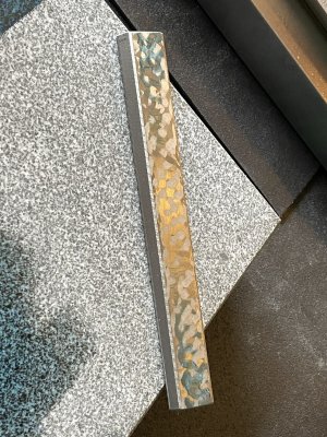
-The front of the gib (thicker end) rocks up and down with very minimal movement of the thinner end, it’s definitely not making full contact with the dovetail
-the side facing the dovetail is not flat as checked against my surface plate

IMG_3087.jpeg

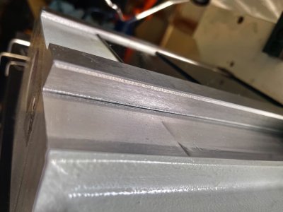
-it seems that the issue is that the gib is pivoting up and down along it’s lengthwise center line, there is evidence of very faint wear on the dovetail. Not sure if it’s visible but there is a slightly darker line along the dovetail towards the top seems to match the cluster of high spots from blueing the gib
IMG_3088.jpeg

I plan to scrape the high spots off at least to get the gib flat on one side and see if the up/down movement goes away and I get the saddle running smooth. Any thoughts?
 

Susquatch

Ultra Member
Administrator
Moderator
Premium Member
Any thoughts?

I am not at all convinced that your gib has an issue. In my mind, the rocking is inconsequential. But I've flogged that with you and others already.

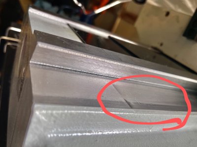
HOWEVER, I DO THINK THAT THIS IS A PROBLEM! I don't believe that this has anything to do with the Gibb.

IMG_3088~2.jpeg
 

Eyecon

Active Member
I am not at all convinced that your gib has an issue. In my mind, the rocking is inconsequential. But I've flogged that with you and others already.
Understood but there is nothing else wrong with it. The dovetails are clear, the gib was stoned on both sides using a precision ground stone and cleaned yet if I fit the gib in so tight that the saddle can’t move, I can still rock it around the Z axis by about .0007-.001”, if it’s not the gib what else can’t it be?
HOWEVER, I DO THINK THAT THIS IS A PROBLEM! I don't believe that this has anything to do with the Gibb.

View attachment 35079
That’s just the reflection from the oil, the bottom of the way is completely smooth
 

Susquatch

Ultra Member
Administrator
Moderator
Premium Member
Understood but there is nothing else wrong with it. The dovetails are clear, the gib was stoned on both sides using a precision ground stone and cleaned yet if I fit the gib in so tight that the saddle can’t move, I can still rock it around the Z axis by about .0007-.001”, if it’s not the gib what else can’t it be?

Well, to be clear, I never said it wasn't the Gibb. Just that a rocking Gibb the way we discussed it, isn't a problem. You could still have Gibb problems. Or or or.....

A gibb (or dovetail) that is fat in the middle might cause the slop you describe even when tight. But don't check it by tightening/loosening the Gibb screw. Try tightening the gibb, locking the cross-slide, installing an indicator, and then rotating the entire cross-slide. You could also try shimming the cross slide.

I do think checking the Gibb and dovetail for flatness. Is a good idea. I just don't think that up down rocking when you tighten the screw matters. I don't know if I mentioned this before, but my Gibb rocks up and down just like yours does when I tighten my screw. But my cross slide doesn't rotate at all.

Did you ever get the new Gibb?

That’s just the reflection from the oil, the bottom of the way is completely smooth

Whew! That looks like a horrible badly worn way in the photo! Glad it's only an oil reflection.
 

Eyecon

Active Member
installing an indicator, and then rotating the entire cross-slide. You could also try shimming the cross slide
Yes that’s exactly how I was measuring. I insert the gib with both adjustment screws removed and I sung the gib in and pull saddle just a little to wedge the gib in place. I’ll try your way as well where I won’t use the adjustment screws but only tighten the locking screw

I don’t really care about the top to bottom movement, I just want the adjust the fit to remove the slop and get smooth movement
 

Susquatch

Ultra Member
Administrator
Moderator
Premium Member

You have to read the entire other thread to understand and I didn't write that very well for anyone that didn't read the other thread.

But basically, I didn't say the Gibb wasn't the issue. I said that the Gibb moving up and down when the Gibb screw is tightened isn't an issue. In my opinion, this Gibb moving when the screw is tightened business was (and still is) a red herring.

But that said, the Gibb could be non planar or have a high spot or or or and therefore the Gibb could be a problem.
 

Susquatch

Ultra Member
Administrator
Moderator
Premium Member
Yes that’s exactly how I was measuring. I insert the gib with both adjustment screws removed and I sung the gib in and pull saddle just a little to wedge the gib in place. I’ll try your way as well where I won’t use the adjustment screws but only tighten the locking screw

I don’t really care about the top to bottom movement, I just want the adjust the fit to remove the slop and get smooth movement

Did you get the new Gibb?

Can you get better photos of the bluing on the Gibb? Or at least explain what we are looking at? It's not clear to me.

Have you tried the cross-slide slop at both ends of its travel as well as at various places in between? And then hope it didn't matter cuz if it does, then your dovetail is suspect........

How much force does it take to get play?

Would you be willing to install two additional lock screws - one at each end? Personally, I wouldn't be willing to do that, but I throw it out there anyway.
 

Mcgyver

Ultra Member
Just that a rocking Gibb the way we discussed it, isn't a problem.
They were disco, not rock. :D :D

Eyecon, I didn't follow the other thread, but I've made and fit several gibs and reconditioned dovetails. That is a straight gib? Its hard to guess what is going on until you start checking geometry, but my first thought was a high point on the dovetails could lead to rock, i.e a moment around the Z. I'm not sure how it could be just based on the gib as with the gib tight, the opposed angled dovetail surfaces should be full contact.

To start, survey the dovetails, i.e. eliminate stuff (my suspicion is that is where the problem is). If you've got a straight edge, check all seven surfaces (that part and its mate, don't care about the one on the backside of the gib) for flatness - that is the first and basic test. Check the parallelism of the four horizontal planes. The smaller mating part can be done on the surface plate and long ways by indicator - surface gauge on one indicating a accurate block on the other along its length. If that all checks out, with some precision pins (dowel pins work well) in the V of each dovetail, mic across them. Check along the dovetail. You may or may not have all the tools for this, its what I think needs to be done and how to do it....without doing all of that you can't isolate where the problem is. If you don't have the stuff we'll figure that out. Sometimes just living with it is a viable option if you can't survey it and/or aren't going rescraping the whole mill.

On that gib you have shown above, what happens if you carefully mic it all the way along? The pattern it shows does not necessarily mean its thicker on the ends, could be just warped. This sort of part is notoriously tough to make without a warp if you don't scrap one side first; its where grinding can't do what scraping can. The reason is, 1/2 of thou of warp is easily overcome by the mag chuck, even with just using the residual magnetism. So, despite careful grinding, on release of the mag chuck, the 1/2 thou warp springs back into existence. Scraping removes the warp because there are no distorting forces when you print it. When I make them, I scrape one side so I know its flat then grind the other. (obviously there are scraping marks on it, however we don't know if these are decoration on a ground surface vs the part being properly scraped)

Point being, don't start removing material, stoning the gib until you what is going on with the geometry of the whole thing.

Small point, but I put an indent or flat bottom holes in the gib where the screws contact it. It gives the end of the screw a flat surface to push against. Grind a tap drill with a flat end (think like a 180 degree point, still needs clearance) and use it carefully to make the seat for the screw.
 
Last edited:

Susquatch

Ultra Member
Administrator
Moderator
Premium Member
Small point, but I put an indent or flat bottom holes in the gib where the screws contact it. It gives the end of the screw a flat surface to push against. Grind a tap drill with a flat end (think like a 180 degree point, still needs clearance) and use it carefully to make the seat for the screw.

Beautiful idea! I don't think it will solve the problem but it would provide peace of mind and be aesthetic too!

You should read the other thread. We got WAAAAY off into a debate on the geometry of a Gibb but I think you would enjoy it! Your talent for splainin things might help too!

Point being, don't start removing material, stoning the gib until you what is going on with the geometry of the whole thing.

This is EXACTLY my feelings on this matter! Identify, Understand, and Validate the problem first. Then figure out how to best fix it or learn to live with it.
 

Eyecon

Active Member
To start, survey the dovetails, i.e. eliminate stuff (my suspicion is that is where the problem is). If you've got a straight edge, check all seven surfaces (that part and its mate, don't care about the one on the backside of the gib) for flatness - that is the first and basic test. Check the parallelism of the four horizontal planes. The smaller mating part can be done on the surface plate and long ways by indicator - surface gauge on one indicating a accurate block on the other along its length. If that all checks out, with some precision pins (dowel pins work well) in the V of each dovetail, mic across them. Check along the dovetail. You may or may not have all the tools for this, its what I think needs to be done and how to do it....without doing all of that you can't isolate where the problem is. If you don't have the stuff we'll figure that out. Sometimes just living with it is a viable option if you can't survey it and/or aren't going rescraping the whole mill.

On that gib you have shown above, what happens if you carefully mic it all the way along? The pattern it shows does not necessarily mean its thicker on the ends, could be just warped. This sort of part is notoriously tough to make without a warp if you don't scrap one side first; its where grinding can't do what scraping can. The reason is, 1/2 of thou of warp is easily overcome by the mag chuck, even with just using the residual magnetism. So, despite careful grinding, on release of the mag chuck, the 1/2 thou warp springs back into existence. Scraping removes the warp because there are no distorting forces when you print it. When I make them, I scrape one side so I know its flat then grind the other. (obviously there are scraping marks on it, however we don't know if these are decoration on a ground surface vs the part being properly scraped)

Point being, don't start removing material, stoning the gib until you what is going on with the geometry
Very valuable info, thanks for taking the time to explain the various tests.


If had a straight edge and a micrometer large enough I would have definitely started with testing the ways before messing around with the gib, however I don’t. Since I measured the slop to be consistent along the Y travel and the machine is brand new, I’m trying to eliminate the only part that’s made by hand i.e. the flaked gib…while has scraping marks i think they did that for oil film retention because none of the surfaces are flat. The flatness it much easier faster thing to correct in my mind that anything else and if ends up seating correctly then we know what’s wrong.

I forgot to mention that I did get a new gib blank and that seats much better although the blank is only roughly machined so I could only confirm the slop is gone when the gib is properly inserted but obviously it’s too long and surfaces are too rough for me to judge how smooth the movement is
 

Eyecon

Active Member
This is EXACTLY my feelings on this matter! Identify, Understand, and Validate the problem first. Then figure out how to best fix it or learn to live with it.
I totally agree but as mentioned above I don’t have a good way of measuring the ways…I really wish I did. Been looking all over for a piece of cast iron or a reasonably priced camel back kit to make a triangular straight edge with no luck. I’ve also been eyeing a 150-300mm interchangeable mic set but way too expensive…..that’s a discussion for another thread :)

Sorry I didn’t answer your question from your pervious post, yes I got the new gib blank and as far as slop goes it does behave perfectly and consistently across the Y travel which is why I started focusing on the old gib. On the previous thread, others suggested that the likelihood of bad way geometry is low and knowing the gib is the only part that’s supposedly hand fitted vs ground or machined I figured someone must have skipped a step at the factory. Again since getting a flat surface is not going to remove much material from the gib and is cheaper and faster than any other option, I figured I’d start there and see if the slop issue is gone…not saying this is the best method, just the easiest/cheapest one available to me. I am open to other suggestions for sure!
 

Eyecon

Active Member
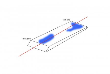
@Susquatch @Mcgyver given what I said above about the blueing pattern I was getting on the sliding gib surface, I see clusters of high spots on either end of the gib with the high spots on the thicker end (the one that had the up and down play) towards the centre of the gib vertically, ie the thinner end makes contact top to bottom, the thicker end makes contact only in the centre so it has less bearing which can explain why it slips up or down when tightened. I also repeated the blueing applying pressure in different places and did the flat slide test against the plate to check the “thirds pivoting” points. The gib certainly pivots around one of the corner on the thinner end and closer got the 1/3 point in the center towards the thicker end, the high spots closer to the center line with various blueing pressure points is also telling me it’s not rocking and I’m not getting false readings. Below is an illustration to help explain what I’m seeing…doesn’t really directly explain the slop because it doesn’t say anything about the taper angle but just indicates the gib is not making full contact with the ways as it should. Not sure if this helps with the troubleshooting Image 2023-06-04 at 10.45 AM.jpeg
 

Mcgyver

Ultra Member
You're welcome, glad to contribute. More stuff to confuse and conflagulate this.... :)

I would not assume new is good. Plus, I'm doubtful the gib is the problem, it doesn't explain the rocking as when locked, the two mating angle dovetail surfaces should be in contact along their length, preventing a moment around the Z and that gib is thin enough that it would easily be pressed into contact with the adjusting screws. What would explain the behaviour would be a variance in the width as measured across the pins, i.e. a bulge in the dovetail would allow that rocking around the Z. However that measurement (across pins) is a bit meaningless without first ascertaining are all surfaces flat, and then are the horizontal surfaces parallel. Trying to decipher the results of a whole bunch of geometry, you methodically do it surface by surface....I might be wrong with the above guess as to the cause, but the tests are the only way to really know what is the cause.

You could make a straight edge, scrape in one surface of angled piece of cast iron. as for the micrometer, you can make a substitute device with indicator - picture like a trammel or caliper with one end an indicator and sweep across the pins looking for the low reading. Kind of like a outside upside down dial bore gauge lol. lots Its only comparative that you need, the actual dimension doesn't matter.

Or live with it.... it may be the best option depending you appetite, vs making/buying surveying tools and fixing whatever errors there are. To identify the problem and fix it though, I'm just not sure how to methodically analyze this, which imo is required, without doing those tests

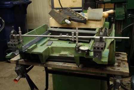
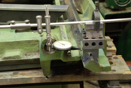
PS, here's some shots of indicating with a trammel set to give you some ideas. The geometry bigger than any mic I had, and indicating was more accurate/more sensitive. I had to scrape the V blocks as well. It was done as a sweep with a tenths indicator and with a gentle touch, produced very consistent readings.

DSC_1642-1300x870-1300x869.JPG


DSC_1644 (Large).JPG
 

Eyecon

Active Member
I would not assume new is good. Plus, I'm doubtful the gib is the problem, it doesn't explain the rocking as when locked, the two mating angle dovetail surfaces should be in contact along their length, preventing a moment around the Z and that gib is thin enough that it would easily be pressed into contact with the adjusting screws. What would explain the behaviour would be a variance in the width as measured across the pins, i.e. a bulge in the dovetail would allow that rocking around the Z. However that measurement (across pins) is a bit meaningless without first ascertaining are all surfaces flat, and then are the horizontal surfaces parallel. Trying to decipher the results of a whole bunch of geometry, you methodically do it surface by surface....I might be wrong with the above guess as to the cause, but the tests are the only way to really know what is the cause.
Makes sense to me but since it’s a brand new machine I do have the option of getting Precision Matthews to do something about it…I just need to be able to prove it to them…they sent me the replacement gib as their suggestion to fix the issue but I didn’t want to fit and cut a new gib without trying the minimal effort corrections first. I do understand and agree that measuring things is the right thing to do I have some of the parts to make a device like the one shown above to measure dovetail parallelism I just don’t know how to measure the ways (the horizontal part) flatness and parallelism without a cast iron straight edge
 

Mcgyver

Ultra Member
@Susquatch @Mcgyver just indicates the gib is not going to be making full contact with the ways as it should. Not sure if this helps with the troubleshooting


I just skimmed the other thread, so it looks like its not a straight gib but is a tapered gib? My mistake at assuming.

Most of what I said still applies, you have to methodically survey to identify the issue. A poorly fit gib creates problems (wear, less rigidity) but it should still pull things together such that the opposite angle dovetail surfaces are in contact. If everything is flat and straight, that contact should prevent any movement. (but are they straight and in contact?)

IF all else is in good shape, flat & parallel, a taper gib is readily scraped into an excellent fit. As I hinted at earlier I doubt PM has hand scraped the gib. Its a bit of decoration done to a ground part and its very difficult to grind a part like that flat. Scrape the side flat that mates on the dovetail, then blue what the opposing side rests against, insert the gib and scrape until its fully bearing. (but I still mantain you can't conclude thats the problem without surveying and I'm kind of doubting it is)
 
Last edited:

Eyecon

Active Member
IF all else is in good shape, flat & parallel, a taper gib is readily scraped into an excellent fit. As I hinted at earlier I doubt PM has hand scraped the gib. Its a bit of decoration done to a ground part and its very difficult to grind a part like that flat. Scrape the side flat that mates on the dovetail, then blue what the opposing side rests against, insert the gib and scrape until its fully bearing. (but I still mantain you can't conclude thats the problem without surveying and I'm kind of doubting it is)
Yes will do and I agree, if things appear flat on the gib side but the issue persists then I can go through the methodical testing, I have a feeling it will be resolved since the ground tapered gib blank removes the slop across the entire range of travel(tested by inserting and removing the gib at the beginning middle and end of travel since it’s very rough to slide the y axis with the gib inserted). I’ll try that and report back. Thanks again to you and @Susquatch for all the suggestions
 

Susquatch

Ultra Member
Administrator
Moderator
Premium Member
I would not assume new is good. Plus, I'm doubtful the gib is the problem, it doesn't explain the rocking as when locked, the two mating angle dovetail surfaces should be in contact along their length, preventing a moment around the Z and that gib is thin enough that it would easily be pressed into contact with the adjusting screws.

I'm not so sure the English in all this discussion is good / clear. It's a lousy language to be sure.

There are two issues here that have been described as rocking. One is the Gibb itself rocking about its bottom rear due to screw friction, and the other is the cross-slide rocking side to side in the dovetails. The theory (which I disagreed with) is that the Gibb rocking allowed the cross slide rocking.

To clarify the Gibb Taper, I believe we are talking about a Gibb that is tapered along its length but not from side to side. The sides are parallel to each other. I asked this question multiple times to ensure that I fully understood the discussion. That doesn't prove a thing though because a good answer requires that the question is clear.

I hope that helps.


Most of what I said still applies, you have to methodically survey to identify the issue. A poorly fit gib creates problems (wear, less rigidity) but it should still pull things together such that the opposite angle dovetail surfaces are in contact. If everything is flat and straight, that contact should prevent any movement. (but are they straight and in contact?)

Exactly.

My primary question here relates to the observation that the cross slide rocks along its entire travel. That is inconsistent with a straight opposite dovetail in good contact.

One thing that "might" help is to find the axis of rotation for the cross slide rocking. This can probably be done by putting a tenths indicator at the front left corner and then again at the rear left corner of the cross slide to find which one is moving and then repeating this check at several locations along the cross slides travel.
 

Eyecon

Active Member
There are two issues here that have been described as rocking. One is the Gibb itself rocking about its bottom rear due to screw friction, and the other is the cross-slide rocking side to side in the dovetails. The theory (which I disagreed with) is that the Gibb rocking allowed the cross slide rocking.
Agree, but the only issue I care about the cross slide rocking despite having the gib inserted…the gib rocking up and down was simply a theory correlating a potentially badly fitted gib to the main issue

To clarify the Gibb Taper, I believe we are talking about a Gibb that is tapered along its length but not from side to side.
Absolutely correct, that’s what I have the sides are parallel height-wise but tapered lengthwise so pushing them in further reduces the space between the mating surfaces.

My primary question here relates to the observation that the cross slide rocks along its entire travel. That is inconsistent with a straight opposite dovetail in good contact
Yes that’s exactly my point about looking at the gib first…not saying something else isn’t also off but assuming parallel ways/dovetails, an incorrectly fitted tapered gib that is not making good contact across its length allows for some wiggle room near one its ends and thus allows for the cross slide to rotate but not slide. For clarity here’s my testing procedure so far: stick the gib in snug with no adjustment screws, measure movement between cross slide and base at one end of the cross slide lengthwise(so close to one end of the gib ), and then repeat on the other other end. What I found is the gib can be inserted so far in that it effectively wedges the cross slide stuck in place i.e. it can no longer move in the Y axis, yet when I measure the rotation around Z axis as described above the cross slide can indeed rotate by .0007-.001” depending on which side I’m measuring.

Again this observation is consistent along the entire travel length, this led me to believe that the ways/dovetails are probably fine and the gib’s geometry is off…likely has a high spot in the middle. Blueing of the moving surface of the gib shows the exact opposite, high spots on the ends and low spot in the middle, so either the cross slide taper is off(it’s pushing the gib out somewhere in the middle across its length) or the gib tapered angle is effectively off (overall or just relatively) causing the low spot I found to actually make contact before either end.

Does this make any sense?
 

Susquatch

Ultra Member
Administrator
Moderator
Premium Member
I just don’t know how to measure the ways (the horizontal part) flatness and parallelism without a cast iron straight edge

You could try making a fixture using gauge blocks and a machinists level. You would be looking for changes at various locations vs others. But I seriously doubt that they are not flat or not parallel.

One of the missing elements in all this is photos of your metrology setups. I've learned to be suspicious of that over the years and it helps to see what is being used and how.
 
Top