Gotta love projects that that are so practical.Here is a few more (mostly) post production photos of my wood stove
...
-
Spring 2024 meetup in Calgary - date Saturday, April 20/2024. discussion Please RSVP Here to confirm and get your invitation and the location details. RSVP NOW so organizers can plan to get sufficient food etc. It's Tomorrow Saturday! you can still RSVP until I stop checking my phone tomorrow More info and agenda
-
We are having email/registration problems again. Diagnosis is underway. New users sorry if you are having trouble getting registered. We are exploring different options to get registered. Contact the forum via another member or on facebook if you're stuck. Update -> we think it is fixed. Let us know if not.
You are using an out of date browser. It may not display this or other websites correctly.
You should upgrade or use an alternative browser.
You should upgrade or use an alternative browser.
In the shop today
- Thread starter Bofobo
- Start date

One piece, the gap is a slot, the cap screws holding my dro scale are the tension screws and the threaded hole is my cross slide connection, further I believe 2 screws because then it clears the centre hole without issue
How much nut material is at the bottom of the slot? Is there a lateral hole (larger than the slot) through the nut at the bottom of the slot? This sounds like something I could do to my cross slide nut.
Bofobo
M,Mizera(BOFOBO)
I did not not remove it to look, it seems to my recollection the slot bottom was solid flat. I kept my scale on the top because I did not wish to mill out the slot on the carriage.... I’m not sure if that’s an answer or notHow much nut material is at the bottom of the slot? Is there a lateral hole (larger than the slot) through the nut at the bottom of the slot? This sounds like something I could do to my cross slide nut.
Bofobo
M,Mizera(BOFOBO)
Hacked my way through a replacement tap holder, it’s not pretty but rustic is beautiful. Starting with some unknown material the old handle was used as a size gauge

The body was made of 1cm bar stock from the estate of an old woodworker in Longview AB,
so of course once I get moving I tend to forget photos but have a few,
free formed the radius, bent one of the handles taking to much material but I got a useable tap wrench again
all in all perhaps 2hours in the shop.

The body was made of 1cm bar stock from the estate of an old woodworker in Longview AB,
 so of course once I get moving I tend to forget photos but have a few,
 free formed the radius, bent one of the handles taking to much material but I got a useable tap wrench again

 all in all perhaps 2hours in the shop.
Bofobo
M,Mizera(BOFOBO)
Ok so I’ve got a noise from my lathe that sounds like a loose collar, has been since I can remember, (I bought new, in crate) no big deal this far but I decided to open the top and peak inside today I found nice clean oil and a gasket made of MASKING TAPE

 so that was great I trimmed it and then noted that there was some pockets of oil in a place above the bearings, thinking that odd I proved them with a pick
now free of the grease that plunged the hole it no longer pools but runs down to lubricate the bearing (checked that) thinking with the tape also removed I was all set, so I put the lid back and ran the machine a few minutes, after which inspected again. I found the oil had not managed to splash on the sides as shown in the pictures in order to lubricate nor saturated the step enough to do so either, so after a few minutes trying to figure a way to assist the oil into these holes, entertaining several ideas including strips of AL, I settled on a bent piece of copper wire
fed into each hole, as the lid is placed it presses down on the wire and goes around the fill bung to the cross in the casting allowing a flow of oil. I tested the idea and after running the machine and removing the lid to check, indeed the wire was letting beads of oil roll into each hole. And soon I guess you tube will get a follow up video for this lathes issue.
so that was great I trimmed it and then noted that there was some pockets of oil in a place above the bearings, thinking that odd I proved them with a pick
now free of the grease that plunged the hole it no longer pools but runs down to lubricate the bearing (checked that) thinking with the tape also removed I was all set, so I put the lid back and ran the machine a few minutes, after which inspected again. I found the oil had not managed to splash on the sides as shown in the pictures in order to lubricate nor saturated the step enough to do so either, so after a few minutes trying to figure a way to assist the oil into these holes, entertaining several ideas including strips of AL, I settled on a bent piece of copper wire
fed into each hole, as the lid is placed it presses down on the wire and goes around the fill bung to the cross in the casting allowing a flow of oil. I tested the idea and after running the machine and removing the lid to check, indeed the wire was letting beads of oil roll into each hole. And soon I guess you tube will get a follow up video for this lathes issue.


 so that was great I trimmed it and then noted that there was some pockets of oil in a place above the bearings, thinking that odd I proved them with a pick

 now free of the grease that plunged the hole it no longer pools but runs down to lubricate the bearing (checked that) thinking with the tape also removed I was all set, so I put the lid back and ran the machine a few minutes, after which inspected again. I found the oil had not managed to splash on the sides as shown in the pictures in order to lubricate nor saturated the step enough to do so either, so after a few minutes trying to figure a way to assist the oil into these holes, entertaining several ideas including strips of AL, I settled on a bent piece of copper wire
 fed into each hole, as the lid is placed it presses down on the wire and goes around the fill bung to the cross in the casting allowing a flow of oil. I tested the idea and after running the machine and removing the lid to check, indeed the wire was letting beads of oil roll into each hole. And soon I guess you tube will get a follow up video for this lathes issue.
Attachments

My apron oil passages were plugged with gunk that looked conspicuously like the brown protection mung they spray on the new machine. Some shafts were never getting oil from day one. Thankfully they were less critical than headstock but lack of lubrication is never a good thing. Some passages I was able to run a wire & solvent through. Out came a waxy turd complete with metal drill swarf. If the passage dead-ends on a critical shaft I'm not sure what the best plan is short of disassembly but solvent, copper wire, blast of air, rinse & repeat is worth a shot If the gallery makes right angles in the casting I wouldnt use a wire just in case. I'm starting to appreciate older/more sophisticated machines with oil tubes that deliver where oil is needed. If there is a problem, pull the tube.
Bofobo
M,Mizera(BOFOBO)
Well I found myself in the vast horde of antiques in the farm garage of my grandfather, I found many things including some future post material as handles are made, but in the mean time I found 2 oil cans one was clean and ready to use with metal innerds but the other needed some love. I started with a wipe down and disassembled it
the balls were corroded and it seemed full of water so I checked the drawer and found 2 new/used from a bike and put it back together, works great now! The pin is just simple so I showed a closer view
 the balls were corroded and it seemed full of water so I checked the drawer and found 2 new/used from a bike and put it back together, works great now! The pin is just simple so I showed a closer view


Bofobo
M,Mizera(BOFOBO)
Today I knurled the ends of my tap holder because I didn’t for some reason, and didn’t take any pictures but I have a bump knurler and on 1/4” stock. Then I moved on to a new tailstock core for my beaver wood lathe.
 The current dead centre is great for a dead centre
but I need to drill because ..... well, of course I do, so i removed the old one took some measurement notes down on my new white board
and turned some nice off cut I had into a JT33 tailstock adapter
with an old beaten 13mm drill chuck
foraged from a pile of junk in my grand fathers farm garage, and that needed a touch of work to even work is not the best but works.
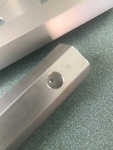
. I also made some aluminum pins for what is practically an antique
and I need a 1/16th rod to hold in place the fabric on the aluminum chassis
, merry Christmas and happy new year
The current dead centre is great for a dead centre
but I need to drill because ..... well, of course I do, so i removed the old one took some measurement notes down on my new white board
and turned some nice off cut I had into a JT33 tailstock adapter
with an old beaten 13mm drill chuck
foraged from a pile of junk in my grand fathers farm garage, and that needed a touch of work to even work is not the best but works.
. I also made some aluminum pins for what is practically an antique
and I need a 1/16th rod to hold in place the fabric on the aluminum chassis
, merry Christmas and happy new year
 The current dead centre is great for a dead centre
 but I need to drill because ..... well, of course I do, so i removed the old one took some measurement notes down on my new white board
 and turned some nice off cut I had into a JT33 tailstock adapter
 with an old beaten 13mm drill chuck
 foraged from a pile of junk in my grand fathers farm garage, and that needed a touch of work to even work is not the best but works.
 . I also made some aluminum pins for what is practically an antique
 and I need a 1/16th rod to hold in place the fabric on the aluminum chassis
 , merry Christmas and happy new year
Bofobo
M,Mizera(BOFOBO)
Got a few new things done and a few started.
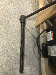
For my belt grinder, being an ongoing endeavour I finally got my wheels made up,
or rather almost, I still need to add pitch to the tracking wheel and I’m struggling to settle on a design for the working end with the scraps I have. I need to scrounge up some nesting square bar and a plate to work with. The drive wheel was bump knurled on an arbour, the tool bearings are 6202 and the guide bearings are 6302.
Sorry boys this is going to be a long read.
I picked up
an old beaver wood lathe a couple years ago and it only has a dead centre
so I decided to make a chuck holder for the tailstock
and might be able to find a good chuck (this one is beaten badly) and live centre.
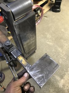
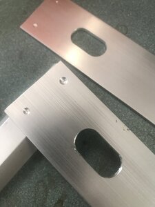
I also needed a rack of some kind for my skidoo, so I used some aluminum 1.5” flat bar and painter pole aluminum hex pipe,
pretty basic no weld and it works great,
I can go 100km over whooped out snow and not loose my chainsaw or bag.
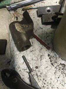
I also felt it was time to do some work on grandfathers old record vise,
it has one jaw,
the other was smashed off many years ago, a time ago I made a replacement jaw
but the old bolts were sheared flush so needed love, I managed to secure the piece in my mini mill with a bolt through the screw hole.
Now I need to wait for my next trip to foothills fasteners to get appropriate bolts.
For my belt grinder, being an ongoing endeavour I finally got my wheels made up,


 or rather almost, I still need to add pitch to the tracking wheel and I’m struggling to settle on a design for the working end with the scraps I have. I need to scrounge up some nesting square bar and a plate to work with. The drive wheel was bump knurled on an arbour, the tool bearings are 6202 and the guide bearings are 6302.
 Sorry boys this is going to be a long read.
I picked up
 an old beaver wood lathe a couple years ago and it only has a dead centre
 so I decided to make a chuck holder for the tailstock


 and might be able to find a good chuck (this one is beaten badly) and live centre.
 I also needed a rack of some kind for my skidoo, so I used some aluminum 1.5” flat bar and painter pole aluminum hex pipe,


 pretty basic no weld and it works great,
 I can go 100km over whooped out snow and not loose my chainsaw or bag.
 I also felt it was time to do some work on grandfathers old record vise,

 it has one jaw,
 the other was smashed off many years ago, a time ago I made a replacement jaw
 but the old bolts were sheared flush so needed love, I managed to secure the piece in my mini mill with a bolt through the screw hole.

 Now I need to wait for my next trip to foothills fasteners to get appropriate bolts.
Attachments
Bofobo
M,Mizera(BOFOBO)
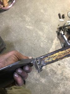
And since Honda likes to rivet it’s oem parts, in this case a brake pedal made of steel on an aluminum arm with an aluminum rivet and no “pedal pad” available only $140 for the whole unit I made a new, bigger bolt on,
and blued it with a torch in place as an experiment.
The material for this was a piece of 3/4” dirtbike shipping create, used a hand grinder vise and fluxcore. And no I didn’t use brass chips for a bed in a holder to blue this part, i did wire wheel the rust off rust though but no other cleaning
 and blued it with a torch in place as an experiment.
 The material for this was a piece of 3/4” dirtbike shipping create, used a hand grinder vise and fluxcore. And no I didn’t use brass chips for a bed in a holder to blue this part, i did wire wheel the rust off rust though but no other cleaning
trlvn
Ultra Member
decided to make a chuck holder for the tailstock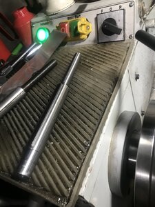
That's a Rockwell Beaver 3400, isn't it? Quite a few years ago, long before I got a metal lathe, a guy was trying to start a little side business providing a replacement part like that except that he milled a #1 Morse taper into it and a knockout bar. I was one of the first guys to throw my hand up so he sent me the prototype. Unfortunately it wouldn't fit my lathe. It was only out by a small amount but was too big to go into the tail stock casting. He was good about it and prepared another that fit very nicely. However, I think it killed his idea of a side business since there was no easy way to determine ahead of time which size was required. Most wood turners don't have an accurate caliper or micrometre. Plus he had to put a lot of machining time into each one. Hard to sell them at a price that valued his time for much.
Craig
Bofobo
M,Mizera(BOFOBO)
Ok, so I’ve got some time now to post my belt grinder build, I’ve used it a few times for some messing around and I’m happy enough with it that I might mount the switch soon. It’s not a VFD just a dryer motor on full.
Starting with the drive wheel,
that’s the oily finished knurling, it’s very nice and consistent though it took some time,
and I did it all with a bump knurle’r.
The finished wheel is directly mounted to the motor shaft, mount and motor from an older treadmill, and made of a 4” solid piece of the “heavy metal” group buy (if anyone knows what it is comment below!!)
I’ll input now that all these materials were salvaged over many years and this is the result of mental planning certain concepts and sudden inspiration building techniques (OA: no plans)
So I started with the bearings I had for the other wheels
and convenient cutoffs for my idler and working wheels.
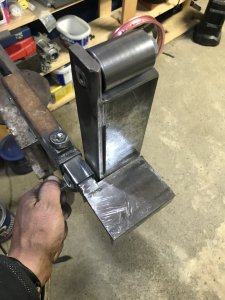
Then I had a long long brain storm about what material I would use for what, considering operational limitations and the functionality of basic setup and additional future tooling. After I had a main body, “I” beam, and a tower
I started with solid platten
and after making the “working face adjustable working angle tool body” I made axles
I peened them I place to test fit and run and made them all hang on a telescopic arm
the adjustment wheel needed to be able to raise and lower for certain angles so I made that happen with these parts
once laid out and welded in place I had to test
I finished off the welding and final wheel setting and later layered these knobs to levers
after which I settled on an old gas shock from my early 90’s Blazer rear window to be my “auto” tensioner (steel is a bit tight and un-lubed)
and because I apparently didn’t take better photos at the end from pure excitement I’ll have to make a second post about it. Now with 12 grades of sanding belts I find Scotch Brite belts and a cork polishing belt. Now to build a coat rack for them all
Starting with the drive wheel,
 that’s the oily finished knurling, it’s very nice and consistent though it took some time,
 and I did it all with a bump knurle’r.
 The finished wheel is directly mounted to the motor shaft, mount and motor from an older treadmill, and made of a 4” solid piece of the “heavy metal” group buy (if anyone knows what it is comment below!!)
 I’ll input now that all these materials were salvaged over many years and this is the result of mental planning certain concepts and sudden inspiration building techniques (OA: no plans)
So I started with the bearings I had for the other wheels
 and convenient cutoffs for my idler and working wheels.


 Then I had a long long brain storm about what material I would use for what, considering operational limitations and the functionality of basic setup and additional future tooling. After I had a main body, “I” beam, and a tower
 I started with solid platten
 and after making the “working face adjustable working angle tool body” I made axles

 I peened them I place to test fit and run and made them all hang on a telescopic arm
 the adjustment wheel needed to be able to raise and lower for certain angles so I made that happen with these parts


 once laid out and welded in place I had to test
 I finished off the welding and final wheel setting and later layered these knobs to levers
 after which I settled on an old gas shock from my early 90’s Blazer rear window to be my “auto” tensioner (steel is a bit tight and un-lubed)
 and because I apparently didn’t take better photos at the end from pure excitement I’ll have to make a second post about it. Now with 12 grades of sanding belts I find Scotch Brite belts and a cork polishing belt. Now to build a coat rack for them all