A couple of years ago in a moment of mental weakness I bought a Craftex 8" bench grinder thinking "how bad can it be"? I turned out to be pretty bad. I mounted it on a stand made from a truck axle shaft, a large 13" brake drum and a 12" brake rotor together these 3 components weigh over 60 lbs. The grinder vibrated so bad it would walk across the floor by it self when running. I tried different stones thinking they were the problem, with no success. A total waste of money. For 2 years it sat un-used because I was so angry with myself. We have a 50 year old Snap-On bench grinder at work and it is smooth as glass, I wondered what makes this one so bad. Finally I decided to try and make it useable.
I removed the guards and stones and measured the run-out on the shaft at both ends. Where the shaft it stepped for the inside washer to register against both side have about .0015" run-out. Not great but not terrible either. I decided that the stamped washers that support the stones must be the problem so I made up some thicker machined ones and still had a lot of lateral run-out at the outer edge of the stones so I decided to get serious and machine all the components to compensate for the shaft runout and build in a provision to balance the stones. Then build an adjustable set of tool rests.
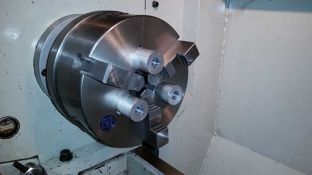
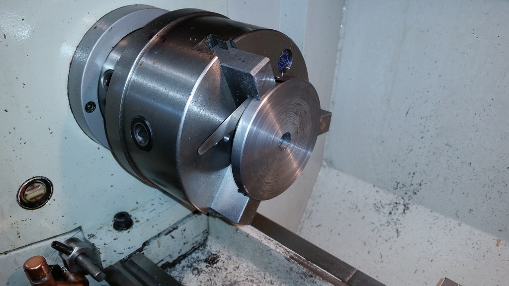
I started by machining the center bushing for both stones from steel and long enough to protrude partway through the outer hub washer. Then I machined and thick inner washer/hub and mounted it to the shaft with no grinding wheel using the wheel center and nut to hold it in place. I made indexing marks so the center bushing and inner washer/hub an always be oriented to the shaft the same way, then measured the lateral run out on the inner washer/hub at the outer edge. The initial .0015" runout was amplified to .008" at the outer edge of the 4" washer/hub I had made. I marked the high spot and mounted it in my lathe chuck with the backing stands and a .008" feeler blade behind the high spot mark.
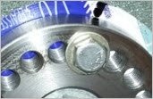
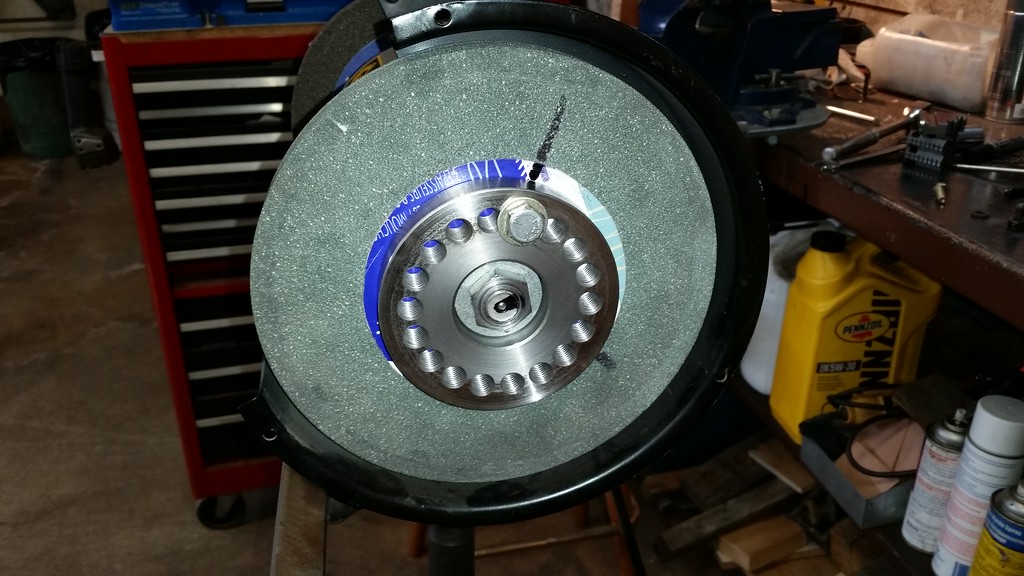
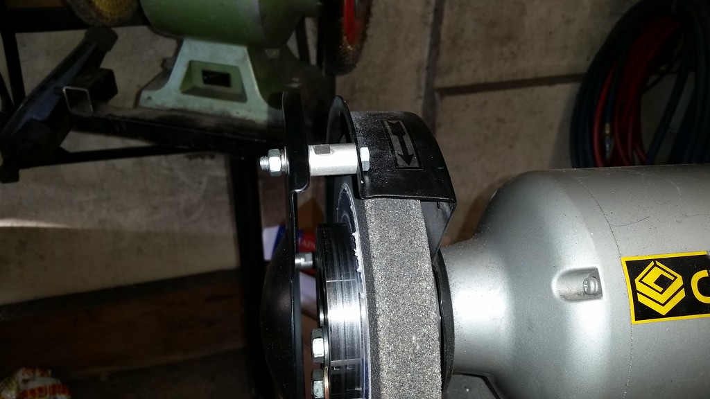
When I remounted the inner washer/hub with indexing marks aligned and measured the runout it is now .001". Close enough. I did this for both sides then machined 2 outer hubs. They are 4" OD and .5" thick, recessed in the center so the nuts will thread onto the shafts and they have eighteen 3/8" holes drilled and tapped around their outer edges. The holes are used to do the balancing. With all the parts assembled there is almost no lateral on the stones but the thing still vibrates like a paint shaker, it's not the shaft runout causing the vibration it's the stones. They are denser in some places . As I tired 2 different set of stones I have to assume this is a common problem.
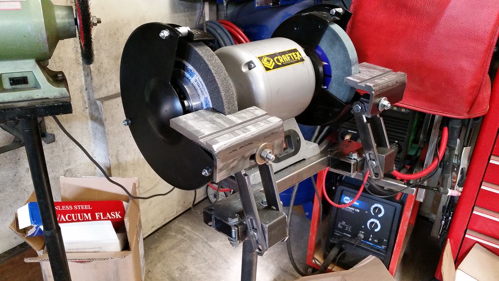
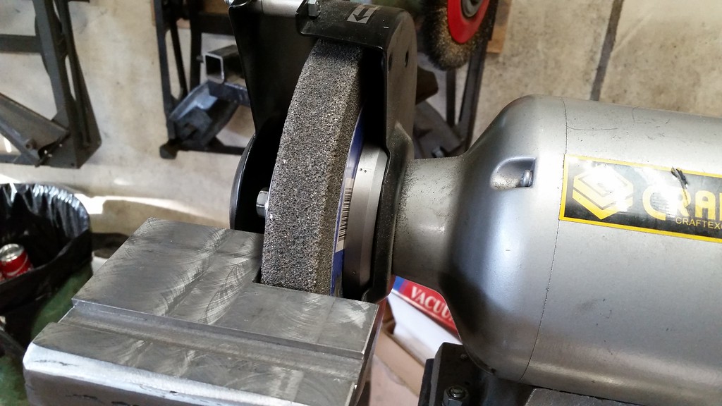
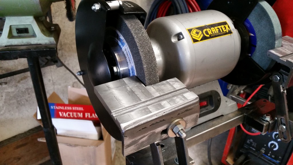
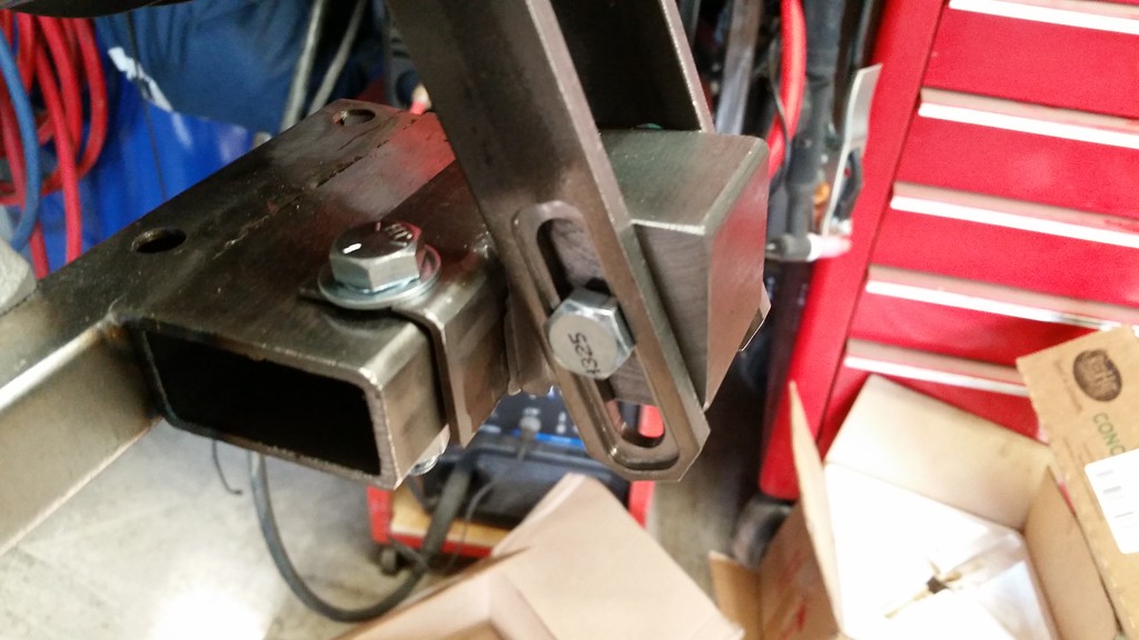
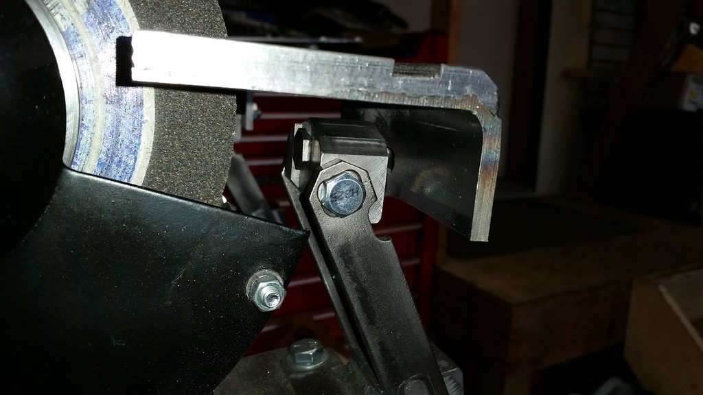
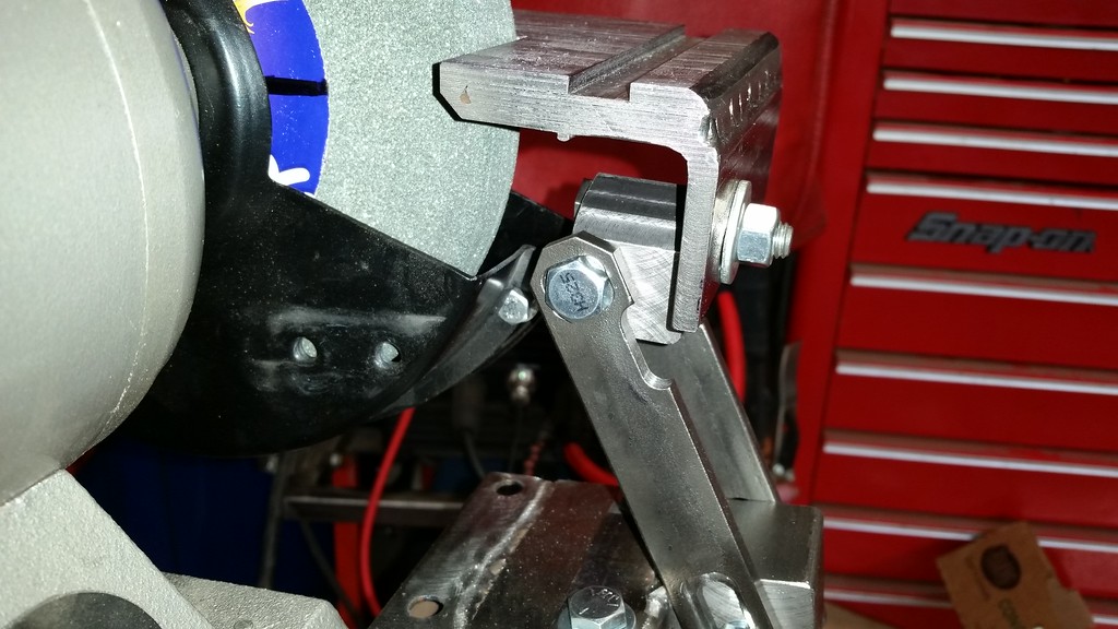
It was easy to see where the heavy spot was on each stone when mounted separately. It would turn the shaft and go to the bottom. I marked the heavy spot on both stones then re-assembled one side and started with one 3/8" by 1/2" bolt and flat washer opposite the heavy spot and noted and huge improvement. By trial and error, adding, reducing and re-locating weight. Once I had one side balanced as well as I could get it I did the same on the other side. I probably spent about 1/2 hour getting the balance tuned so achieve the lowest vibration level. The grinder is now super smooth so I moved onto building adjustable tool rests. I used some pieces of the same 4" square tube I used on my welding table with the top side being weld laminated to 1/2" thickness to allow a mitre groove 1/8" deep and 1/2" wide to be machined in each rest top. I also had to add spacers to be able to install the outside guards. With the heads of the bolts sticking out it would be easy to injure yourself there so the guards are a must. The bracket mounting bolt positions were all machined to be tightened with one hand, no back up wrench required. Here are a few pics, not fancy but it works.
In the end this was a heck of a lot of work but it turned the Busy Bee grinder into something that actually can be used for grinding instead of a doorstop. I might even take it all apart and paint the stand now.
I removed the guards and stones and measured the run-out on the shaft at both ends. Where the shaft it stepped for the inside washer to register against both side have about .0015" run-out. Not great but not terrible either. I decided that the stamped washers that support the stones must be the problem so I made up some thicker machined ones and still had a lot of lateral run-out at the outer edge of the stones so I decided to get serious and machine all the components to compensate for the shaft runout and build in a provision to balance the stones. Then build an adjustable set of tool rests.
I started by machining the center bushing for both stones from steel and long enough to protrude partway through the outer hub washer. Then I machined and thick inner washer/hub and mounted it to the shaft with no grinding wheel using the wheel center and nut to hold it in place. I made indexing marks so the center bushing and inner washer/hub an always be oriented to the shaft the same way, then measured the lateral run out on the inner washer/hub at the outer edge. The initial .0015" runout was amplified to .008" at the outer edge of the 4" washer/hub I had made. I marked the high spot and mounted it in my lathe chuck with the backing stands and a .008" feeler blade behind the high spot mark.
When I remounted the inner washer/hub with indexing marks aligned and measured the runout it is now .001". Close enough. I did this for both sides then machined 2 outer hubs. They are 4" OD and .5" thick, recessed in the center so the nuts will thread onto the shafts and they have eighteen 3/8" holes drilled and tapped around their outer edges. The holes are used to do the balancing. With all the parts assembled there is almost no lateral on the stones but the thing still vibrates like a paint shaker, it's not the shaft runout causing the vibration it's the stones. They are denser in some places . As I tired 2 different set of stones I have to assume this is a common problem.
It was easy to see where the heavy spot was on each stone when mounted separately. It would turn the shaft and go to the bottom. I marked the heavy spot on both stones then re-assembled one side and started with one 3/8" by 1/2" bolt and flat washer opposite the heavy spot and noted and huge improvement. By trial and error, adding, reducing and re-locating weight. Once I had one side balanced as well as I could get it I did the same on the other side. I probably spent about 1/2 hour getting the balance tuned so achieve the lowest vibration level. The grinder is now super smooth so I moved onto building adjustable tool rests. I used some pieces of the same 4" square tube I used on my welding table with the top side being weld laminated to 1/2" thickness to allow a mitre groove 1/8" deep and 1/2" wide to be machined in each rest top. I also had to add spacers to be able to install the outside guards. With the heads of the bolts sticking out it would be easy to injure yourself there so the guards are a must. The bracket mounting bolt positions were all machined to be tightened with one hand, no back up wrench required. Here are a few pics, not fancy but it works.
In the end this was a heck of a lot of work but it turned the Busy Bee grinder into something that actually can be used for grinding instead of a doorstop. I might even take it all apart and paint the stand now.