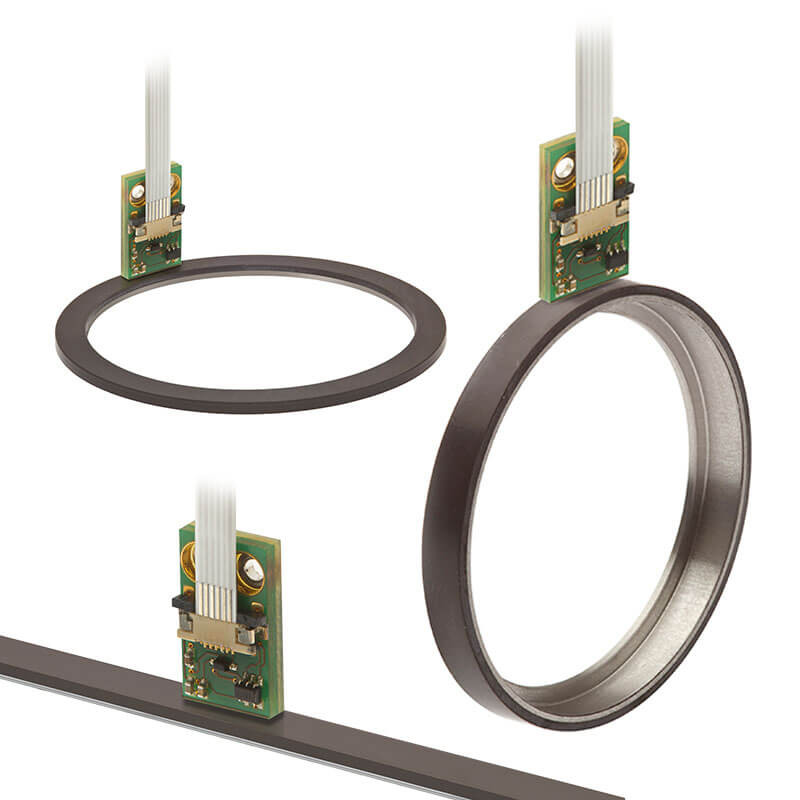
Am I to understand you're ripping the read head out of their little aluminium blocks? I've been tempted to do this, but loathe to be the first to kill a $100 part...
I have yet to decide if I will go the same way as the "naked gopro" by stripping out a chinese read head, or if I will purchase a pcb and dro control designed by this
fellow in the UK, or if I will just design my own entirely.
I have a feeling that the chinese pcb orientation is the opposite of what I want, but I haven't yet cracked one open. The PCBs by Nicholas Bull are the right orientation, but the availability is an issue, and I doubt he has the time to do a pcb design revision.
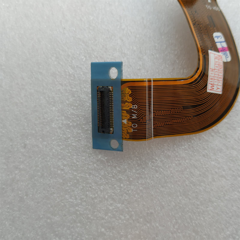
but yes the goal is a micro-read head to embed into pocket machined in the cross slide, and the problem to be solved is to connect to the read head with the smallest form factor possible and the least machining of the original equipment, some of which has next to no machining allowance to the parts.
The UK fellow probably just reverse engineered these read heads to change the orientation. He uses the same chip at the very least.
I think these RLS chips are the same orientation as the German origin chips in the Ditron DROs. Stupid if you ask me.
In all likelihood I'll just ask my buddy to reverse engineer the pcb to the same specs as the chinese heads but with the flat reading orientation I desire. then I can use them plug and play on any system out there.