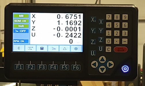
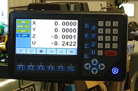
As many will know, I finally finished installing the last part of my DRO - the quill axis. It is set to work together with my knee axis for a combined Z + Quill Readout.
Ever since its completion, I've been futzing around making slow progress on a job that I saved specifically for the DRO. In fact, you could almost say the job was part of the reason I got the DRO in the first place.
A long time ago, I put together a triple front spider for concentricity work. The spider allows you to align a work object totally concentric to the axis of the spindle. But is a beast to use because it had to be held and aligned in a four jaw before a part could be installed and aligned in the spider. A few years after making the spider assembly, I bought a D1-5 back plate for it so it could be directly used without the 4 jaw. The problem was the screws that had to be installed in the hub recess of the backplate without affecting the spindle attachment. To be honest, I had very low confidence in my ability to layout a perfect 6 element bolt circle using the tools I had at the time.
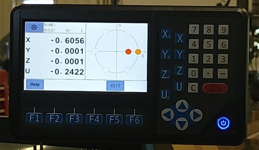
On the other hand, it was a perfect job for the circular array (bolt circle) function of a DRO.
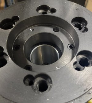
Only 4 of 6 screws installed so far. But good enough for a photo. Two more to go.

Very happy so far. Here is a shot of the DRO in action.

Some challenges were encountered.
The stem of my 1/4-28 taps measures 0.254 - too big to enter a 1/4" hole. But I needed a long screw hole to fit through the cast-iron backplate and have enough thread to maintain a good solid hold on the spider. I suppose with the DRO I could have machined the two parts separately, but again I had no confidence. In time I may charge ahead - but for now it's crawl before you walk before you run.
A bigger socket head cap screw would have been better but that might weaken the backplate casting too much. A 1/4 inch screw is actually plenty strong enough though, so a compromise was made. I drilled out an extra 1/4 inch of depth to accomodate the tap shaft with a 17/64ths drill. This was plenty but the 17/64 drill bit just wouldn't fit a 1/4" ER32 collet. I had to use a 5/16 collet. That worked but it felt just awful tightening that collet that much. I'm going to see if I can find a 9/32 collet. 32nds ER32 collets are not common and are not listed but who knows - they may exist somewhere. I do enough 1/4" tapping that it's worth trying to find the collet. If not, I may grind a 1/4" Collet out a bit instead.
Most of the drilling and tapping required depth control. The 4th axis of the DRO came in really handy for that. The biggest problem was anticipated - calibrating the Z Axis zero. Basically, I touched off the face of the D1-5 spindle nose recess and set zero there for each increasingly larger tool used. I maintained a chart of depths for each phase - tap drill, screw shaft clearance, tap shaft clearance, and finally socket head countersink depth. All tapping was done manually.
When I'm all done, I'll clean and reinstall the cam-lock studs and try it out.
All-in-all, I'm very happy. So far - so good...... Nice DRO.
Ever since its completion, I've been futzing around making slow progress on a job that I saved specifically for the DRO. In fact, you could almost say the job was part of the reason I got the DRO in the first place.
A long time ago, I put together a triple front spider for concentricity work. The spider allows you to align a work object totally concentric to the axis of the spindle. But is a beast to use because it had to be held and aligned in a four jaw before a part could be installed and aligned in the spider. A few years after making the spider assembly, I bought a D1-5 back plate for it so it could be directly used without the 4 jaw. The problem was the screws that had to be installed in the hub recess of the backplate without affecting the spindle attachment. To be honest, I had very low confidence in my ability to layout a perfect 6 element bolt circle using the tools I had at the time.
On the other hand, it was a perfect job for the circular array (bolt circle) function of a DRO.
Only 4 of 6 screws installed so far. But good enough for a photo. Two more to go.
Very happy so far. Here is a shot of the DRO in action.
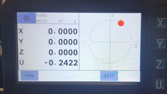
Some challenges were encountered.
The stem of my 1/4-28 taps measures 0.254 - too big to enter a 1/4" hole. But I needed a long screw hole to fit through the cast-iron backplate and have enough thread to maintain a good solid hold on the spider. I suppose with the DRO I could have machined the two parts separately, but again I had no confidence. In time I may charge ahead - but for now it's crawl before you walk before you run.
A bigger socket head cap screw would have been better but that might weaken the backplate casting too much. A 1/4 inch screw is actually plenty strong enough though, so a compromise was made. I drilled out an extra 1/4 inch of depth to accomodate the tap shaft with a 17/64ths drill. This was plenty but the 17/64 drill bit just wouldn't fit a 1/4" ER32 collet. I had to use a 5/16 collet. That worked but it felt just awful tightening that collet that much. I'm going to see if I can find a 9/32 collet. 32nds ER32 collets are not common and are not listed but who knows - they may exist somewhere. I do enough 1/4" tapping that it's worth trying to find the collet. If not, I may grind a 1/4" Collet out a bit instead.
Most of the drilling and tapping required depth control. The 4th axis of the DRO came in really handy for that. The biggest problem was anticipated - calibrating the Z Axis zero. Basically, I touched off the face of the D1-5 spindle nose recess and set zero there for each increasingly larger tool used. I maintained a chart of depths for each phase - tap drill, screw shaft clearance, tap shaft clearance, and finally socket head countersink depth. All tapping was done manually.
When I'm all done, I'll clean and reinstall the cam-lock studs and try it out.
All-in-all, I'm very happy. So far - so good...... Nice DRO.
Last edited:

