• Scam Alert. Members are reminded to NOT send money to buy anything. Don't buy things remote and have it shipped - go get it yourself, pay in person, and take your equipment with you. Scammers have burned people on this forum. Urgency, secrecy, excuses, selling for friend, newish members, FUD, are RED FLAGS. A video conference call is not adequate assurance. Face to face interactions are required. Please report suspicions to the forum admins. Stay Safe - anyone can get scammed.

DRO on Round Column Mill Z axis

Tomc938

Ultra Member
About a year ago I picked up a three axis DRO off AliExpress.

The X and Y axis were fairly easy to mount on my RF 30 clone.

I'm struggling with exactly how I should mount the Z axis.

If anyone has pictures of how they have mounted the Z axis on there around column mill I would appreciate if you could post a couple of pictures.

Thanks!

Tom
 
Z- Scale.....

ZSCALE.JPG
 
 
I'm struggling with exactly how I should mount the Z axis.

When you say Z, do you mean the head moving on the column or the spindle?

I assumed there was no point doing it on the column because of the way the head affects x & y when it is moved.

If I keep my round column mill/drill I will only do it on the spindle.

Here is how I did the spindle Z on my Hartford - hopefully it might spawn some ideas for you. I took the liberty of linking you straight to the quill part of the install.

Post in thread 'Installing a DRO on a Hartford Bridgeport Clone.' https://canadianhobbymetalworkers.c...n-a-hartford-bridgeport-clone.4852/post-85016
 
This is how I did it with a 6" scale, I just made a little bracket that hugs the quill. Yikes pretty rough looking, that was one of the first things I did when I picked up my mill it could use some cleanup.
IMG_1408.JPG
IMG_1409.JPG
IMG_1410.JPG
 
Last edited:
When I got this machine, the Z axis DRO install was badly done and limited the quill travel to about 3.5 inches instead of the just over 5 inches it ought to have. The following is an in-process shot from re-doing it.

IMG_4671_trial_fit.jpg


Note that the scale (in the black accordion tube) needs to extend down past the bottom of the head casting in order to get full travel of the encoder head. I first attached a 1/8" aluminum 'backer' to the head that was a bit long. That let me verify how long everything had to be at full extension and then cut the parts to the final length.

Craig
 
I take it that is a forward-reverse switch on your mill? Did you add that or did yours come that way? That's something I might want to add to mine.

Craig

Factory original FWD/REV drum switch. Has since been deleted after changing over to a 3 phase motor and VFD.
 
When you say Z, do you mean the head moving on the column or the spindle?

I assumed there was no point doing it on the column because of the way the head affects x & y when it is moved.

If I keep my round column mill/drill I will only do it on the spindle.

Here is how I did the spindle Z on my Hartford - hopefully it might spawn some ideas for you. I took the liberty of linking you straight to the quill part of the install.

Post in thread 'Installing a DRO on a Hartford Bridgeport Clone.' https://canadianhobbymetalworkers.c...n-a-hartford-bridgeport-clone.4852/post-85016
Yeah, should have said on the quill. The "Z" on the column is just for getting me into the right ball-park, and totally messes up the X and Y.

Thanks for the link and the arrow showing where the sensor is mounted. (I was looking for a bit as it is different from what came with my DRO scale.
For the most part, no issues. Does your DRO have an anti-shake option?
I'll have to check on the anti shake...thanks for the tip!
 
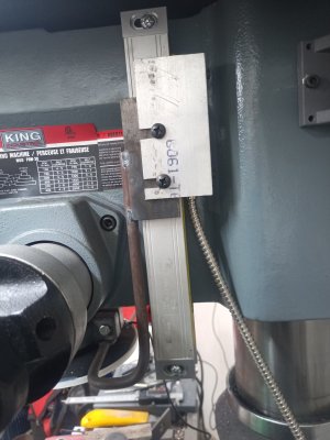
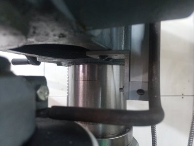
This is how I have mine mounted....it's the only axis that doesn't have a flicker from vibration

It was also one of the first few things I did on the mill...I had intentions of prettying it up...but we all know how that goes

IMG_20230220_145834_280.jpg
IMG_20230220_145811_593.jpg
 
Back
Top