• Spring 2024 meetup in Calgary - date Saturday, April 20/2024. discussion Please RSVP Here to confirm and get your invitation and the location details. RSVP NOW so organizers can plan to get sufficient food etc. It's Tomorrow Saturday! you can still RSVP until I stop checking my phone tomorrow More info and agenda
  • We are having email/registration problems again. Diagnosis is underway. New users sorry if you are having trouble getting registered. We are exploring different options to get registered. Contact the forum via another member or on facebook if you're stuck. Update -> we think it is fixed. Let us know if not.
  • Spring meet up in Ontario, April 6/2024. NEW LOCATION See Post #31 Discussion AND THE NEW LOCATION

CNC Gantry Mill/Router

gerritv

Gerrit
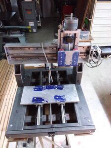
I started building this in Feb this year after seeing Stefan Gotteswinter's Stepmores SM4040 in action on YT. The machine is just the right size for my perceived needs.

Built up from 1/8" wall 2x4, 2x2 and 1x2 steel tube. Joints are with T Bolts, furniture style. made from 1/2" CR steel. Main assembly is with 5/16-16 SHCS.
The Z axis is built up of aluminum plate, X Axis is 6x2 aluminum U Channel salvaged from Univac II tapedrive from 1958 (I worked for Univac at Ont Hydro and helped scrap the Univac II's they had in 1968) A true justification for 'you never know when you might need it' hoarding.
Ball screws are Thomson 1/2 salvaged from a 1980's digitizer from Bata Shoes as are the Y axis rails and bearings.
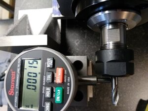
Spindle will be water cooled ER20 via Aliexpress.
Software is Pathpilot using a Mesa 7I92h and an old PMDX-132 bob.
Should be running sometime in October at present slow rate of progress.
20200914_154924 (Custom).jpg
 

RobinHood

Ultra Member
Premium Member
Very nice.

is that a heat treating oven on the floor showing in the picture just below the gantry stepper motor?
 

gerritv

Gerrit
Initially to make reproductions of displays for a Univac II console panel that my brother and I are 're-animating'. 12 display modules, each with 10 thin edge lit acrylic with a number engraved on it.
Then back to the Rudy Kouhoupt marine engine. No doubt along the way I will be making fixtures on it.

There are some other engines on my list that would benefit from CNC. My small horizontal mill is not up to a lot of the required machining, largely due to everything being a workholding challenge on it.

Gerrit
 

gerritv

Gerrit
It is sooo close to running. But house and yard has prioirty, and helping a friend build a new fence/gate. Next week is clear so expecting to have this running on Pathpilot very soon.
After a ton of layout, pin-prick followed by centre punch I am seriously impressed with what you can do on a drill press. Almost nothing on this build was done with my milling machine except cross drilling the t-bolts. The 16 holes for the bed subplate all lined up!
Shop made counter bore did the trick to get the SHCS recessed.

gerrit
 

Attachments

  • IMG_20201007_183114 (Custom).jpg
    IMG_20201007_183114 (Custom).jpg
    92.5 KB · Views: 9

RobinHood

Ultra Member
Premium Member
I guess you are measuring TIR of the endmill shank in your spindle you got off AliExpress?

I would say that that is very good. My 1968 BP mill gets 2 to 2.5 tenths TIR at the endmill shank with an R8 to ER32 adapter and appropriate collet.
 

PeterT

Ultra Member
Premium Member
I could be. But an appropriate prior check step is remove the collet & EM shank & measure the ID cone. If you get a similar number you are probably good. But by introducing extra elements all you read is the collective whole. Potentially you can have cancellations or exaggerations depending on how they align/misaligned.

For example lets say we know for sure spindle ID cone is off 0.001". And collet/shank is also off by 0.001". Put them together one way minimized & they cancel 0.000" Put them together phased a different maximized way & you get 0.002". Anything in between yields different relative number.

I've heard of some good numbers on spindles in that caliber. I've also read some amazing numbers in the cheapo 500w spindles & then they show cheapo skateboard bearings in there so hard to visualize, or will it stay that way.

I'd like to see how you circulate cooling water & related issues. Is it just tap water & waste system you just dump the bucket or certain additives or...?
 

gerritv

Gerrit
Yes I know there are correct/best practices for measuring runout, however I wanted a sanity check before going any further. My manual mill has .006" on a good day so already happy that this is possible.
Water will be dumped/recirculated in a large square pail. The motor doesn't really hewat up much so far so not worried too much. I do owever have to wiat for the correct voltage pump to arrive, they sent a 220v one, and no 220 in the shop.

In the meantime sorted out a bunch of issues and did some test cuts in al and cold rolled steel. Very pleased. Lots more to do before I run any programs though.
 

Attachments

  • IMG_20201018_181215 (Custom).jpg
    IMG_20201018_181215 (Custom).jpg
    96.9 KB · Views: 5

Tom O

Ultra Member
Looking good have you tried tapping on the cutter to see if it improves the run out? NYC did a video on it.
 
Top