• Spring 2024 meetup in Calgary - date Saturday, April 20/2024. discussion Please RSVP Here to confirm and get your invitation and the location details. RSVP NOW so organizers can plan to get sufficient food etc. It's Tomorrow Saturday! you can still RSVP until I stop checking my phone tomorrow More info and agenda
  • We are having email/registration problems again. Diagnosis is underway. New users sorry if you are having trouble getting registered. We are exploring different options to get registered. Contact the forum via another member or on facebook if you're stuck. Update -> we think it is fixed. Let us know if not.
  • Spring meet up in Ontario, April 6/2024. NEW LOCATION See Post #31 Discussion AND THE NEW LOCATION

6 by 18 Surface Grinder

RobinHood

Ultra Member
Premium Member
This machine "jumped" on my trailer a while back
IMG_0325.JPG

It has external hydraulics (large tank) and coolant (small tank). In front is a de-mag that came with it.

Coolant and hydraulic motors did not run; here is why (hyd motor shown):
IMG_0332.JPG

The bearing was full of shmoo. Luckily I don't think they ever ran them like that; it would have spun the bearings - but they were not. Replaced them and cleaned the inside; now they run like a top.

Here was the reason for a spindle vibration I got:
IMG_0350.JPG

This is the "CJ" style urethane spider from the love-joy type coupling between the spindle and its drive motor. I have already glued the broken off ears back on (you can just see the one @ about 10'o-clock position). The spider is an odd-ball size, of course, and not available off the shelf.... Hence the drawing and the home made cutter.

Here is the cutter in use:
IMG_0353.JPG

I made Delrin spiders first to see if my geometry was correct before I attempted it in rubber...
IMG_0372.JPG

If rubber does not last, I now have an accurate part that I can make a mold from and cast a spider out of liquid urethane, if required.

Here is one installed on the motor side of the coupling:
IMG_0373.JPG

Runs smoothly now (I did also replace the bearings in the motor, while I was at it).

Also made a couple knobs for the control panel (the alu ones in the bottom row) - they were missing; and a wheel arbor pulling tool:
IMG_0343.JPG

IMG_0329.JPG

All components of the grinder work, just not at the same time: I am waiting for my shop RPC so the machine can be powered properly with 3 phase, 220 V.

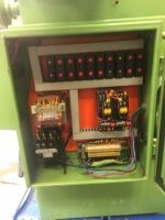
Here is a pic of the "brain" of the grinder:
IMG_0318.JPG

There are a bunch of limit switches and electrically/mechanically controlled hydraulic valves that complement this panel. That is/was my primary reason for not running the machine with just 3 appropriately sized VFDs (one for each motor) and re-wiring the whole kit and caboodle.
 

Attachments

  • IMG_0314.JPG
    IMG_0314.JPG
    44.7 KB · Views: 5

RobinHood

Ultra Member
Premium Member
Question for the administrators/moderators:

As you can see, I used full size images in this post (except for the last pic, which I did not really want, but forgot to hit delete before I posted....).

Is that the preferred method or just use thumbnails as I did previously?
 

Dabbler

ersatz engineer
Nice Grinder! With the hydraulic system, your ways are bound to be in great shape! I seriously considered 2 INGAR grinders before my B&S came along.

- Did you make a static balancing arbor or did it come with one?
 

PeterT

Ultra Member
Premium Member
Re pictures, I think I made a suggestion once upon a time to have a max picture attachment size just as a safeguard to prevent the occasional 'Big MB oops' that got attached by mistake. I know, I've done it a few times myself. Personally I like thumbnails as a default. Big reason is if I open a picture heavy post on my phone it tends to cough a fur ball vs. selecting thumbnails individually. Second, its nice to read the text which typically relates to attached pics & sometimes tahtgets buiried in among the big images. In terms of forum standards I'll leave that to the developer types.

Anyway, blah-blah... nice machine! You guys are not afraid to roll up your sleeves & tackle these rebuild projects. I'm impressed.
 

RobinHood

Ultra Member
Premium Member
Did you make a static balancing arbor or did it come with one?
I have not yet made a balancer; it did not come with one.

The ways are lubricated with a manual Bijur style oiler - it did/does work and there seems no appreciable wear in any of the sliding parts.

Since I have not fully hooked it up to power (because of the lack of a RPC), I have not ground anything yet. I only have one arbor - planning on making some. I do have a good selection of grinding wheels though.
 

RobinHood

Ultra Member
Premium Member
Re pictures: thanks for the comment! I did notice that when I was checking the post as "guest" ( ie not logged in), the pics where sideways. I will use the thumbnails from now on as they seem orientated properly all the time.

Tearing into a machine is a lot of fun for me as I learn how it all works. Its always amazing to see how engineers of days long gone have solved problems...
 

kylemp

Well-Known Member
How did you make your cutter profile for the spider on this?
Have you got it all up and running?
 

RobinHood

Ultra Member
Premium Member
A) Cutter

Please refer to the hand drawing below:

IMG_0595.JPG

I created this using the broken urethane spider and the two metal mating couplings. You can see that the "teeth" are basically sectors of circles whose centres are located on the perimeter of other concentric circles. Specifically, item 4 with a diameter of 28 mm will give the correct side profile of the cutter to be made. I have a Dumore Tool Post Grinder with lots of grinding wheels of various sizes. I dressed on of these to a diameter of 28 mm. Also from the drawing you can see that the maximum linear distance between two adjacent teeth at their apex is 0.716 in. So I decided to use a piece of on hand 3/4" drill rod. I first milled a flat on the end to exactly 1/2 the diameter =>3/8" by clamping the round piece horizontally in the vice. I then set up the tool post grinder on the mill table and mounted the drill rod in a 3/4" collet in the mill spindle. I had it turning slowly and fed in the grinding wheel from the side to start shaping the sides on the split blank. See pic below (the camera did not like the LED ring lighting on the mill quill - hence the blue tint).

IMG_0348.JPG

The relieve required to make it cut is automatically obtained by it rotating while being formed. The principle behind this is similar to an engraving cutter whose point is also first spilt and then the side profile shaped. I believe Stefan Gotteswinter has a video on sharpening/making cutters of this type.

I honed the cutting edges and did not bother to harden it since I was only going to cut Delrin and, later, Rubber.

B) Operation

Yes, it is up and running. I had to straighten the hydraulic push rod on the table cylinder because it was bent and binding up. That was accomplished by dismantling the cylinder and putting the 12 mm diameter rod between centres in the lathe and measuring run out. I pushed on the high spots by hand to straighten it.

I have about 1/2 to 1 thou out of flat on my mag chuck (across the diagonal). Was to be expected as I had the grinder all apart for cleaning. Need to grind that out. Have not done so because my machine is on casters (due to severe lack of shop space) and would prefer to wait until I can find a permanent location for the grinder so I can set it firmly on the floor. I have used it for short pieces as that bit of run out is barely noticeable on them.
 
Top