I stole the idea for this tailstock from another forum and made a few changes in the plans. I wanted to build it all from scrap parts but I had to buy a length of 2" round aluminum from the "drops" bin at Metal Supermarket.
I don't have any pictures of the machine work in progress, just the finished parts.
I mounted the 2" round aluminum in my 4 jaw chuck and bored the hole off-center for the tailstock spindle and the stud for the adjuster nut. Then I milled 2 flat sides on it and split one end with a slitting saw mounted in the mill and drilled a couple of 5/16" holes for the through bolts. I milled a flat on the bottom side and drilled and tapped a hole intersecting the spindle bore for a depth stop screw. I turned the spindle from 3/4" CRS with a taper on one end and a slot for the adjuster nut on the other. Then I milled a slot for the travel stop screw into the spindle. I drilled and tapped a hole in the split end for a pinch bolt.


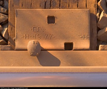
The scrap metal for the sides and bottom was purchased by the pound from a scrap metal dealer who empties the metal bin where I used to work. You may recognise the source, all 3 of the pieces were rough cut from the same part with my band saw then machined on the mill. After the 3 parts were machined they were clamped together and the holes were drilled for the through bolts. The flat side were done with my shop built flycutter and the rest was done with a 2" indexable end mill or a 1/2" end mill.


The adjuster nut was made from a piece of 1-1/4" CRS with a 3/8" threaded hole and a knurled OD as well as a slot to match the one in the spindle so it pulls or pushes the spindle.


The sides and bottom were bolted together and the bottom was milled flat with them assembled.


The spindle body it adjustable for height and there is also a pic of the tailstock in use before I finish machined the outer part of the side pieces.


I don't have any pictures of the machine work in progress, just the finished parts.
I mounted the 2" round aluminum in my 4 jaw chuck and bored the hole off-center for the tailstock spindle and the stud for the adjuster nut. Then I milled 2 flat sides on it and split one end with a slitting saw mounted in the mill and drilled a couple of 5/16" holes for the through bolts. I milled a flat on the bottom side and drilled and tapped a hole intersecting the spindle bore for a depth stop screw. I turned the spindle from 3/4" CRS with a taper on one end and a slot for the adjuster nut on the other. Then I milled a slot for the travel stop screw into the spindle. I drilled and tapped a hole in the split end for a pinch bolt.


The scrap metal for the sides and bottom was purchased by the pound from a scrap metal dealer who empties the metal bin where I used to work. You may recognise the source, all 3 of the pieces were rough cut from the same part with my band saw then machined on the mill. After the 3 parts were machined they were clamped together and the holes were drilled for the through bolts. The flat side were done with my shop built flycutter and the rest was done with a 2" indexable end mill or a 1/2" end mill.


The adjuster nut was made from a piece of 1-1/4" CRS with a 3/8" threaded hole and a knurled OD as well as a slot to match the one in the spindle so it pulls or pushes the spindle.


The sides and bottom were bolted together and the bottom was milled flat with them assembled.


The spindle body it adjustable for height and there is also a pic of the tailstock in use before I finish machined the outer part of the side pieces.


